Use Analogue Sensors with Raspberry Pi
Connect an MCP3008 to a Raspberry Pi with a light dependent resistor
Written By: Cherie Tan
Difficulty
Easy
Steps
24
While the Raspberry Pi can control digital inputs and outputs, what if you wanted to read analog signals?
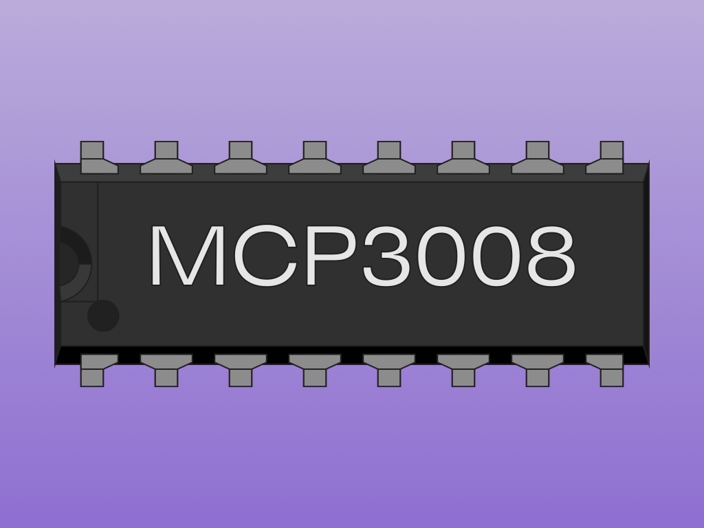
In this guide, we'll connect up an Analogue to Digital Converter (the MCP3008) to the Raspberry Pi, and then connect a light dependent resistor (LDR) to it.
Complete this guide to learn how to connect analogue sensors to the Raspberry Pi.
Complete this guide to learn how to connect analogue sensors to the Raspberry Pi.
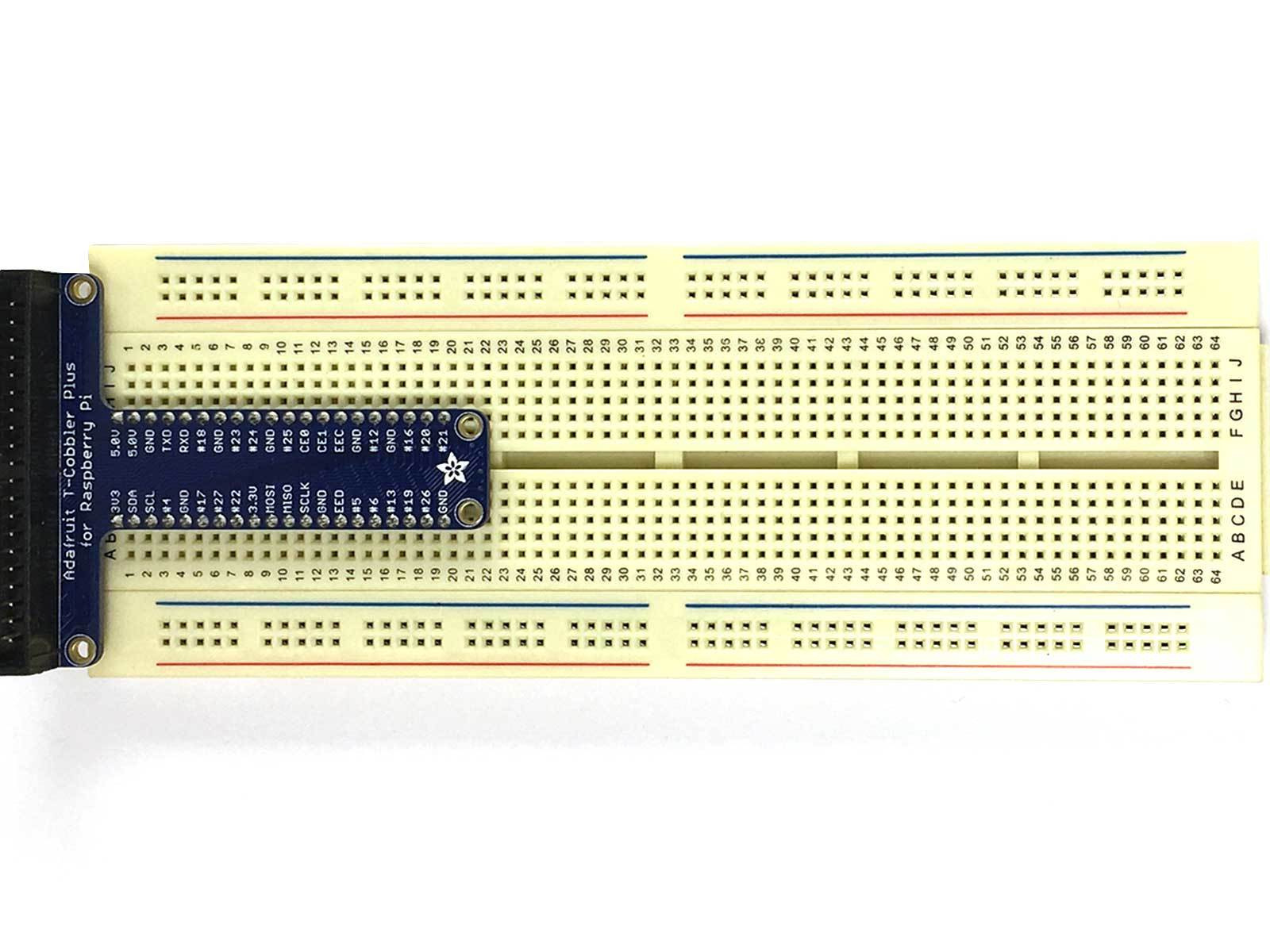
First, connect the T-Cobbler Plus breakout board to the breadboard.
Attach it so that one side of it is between C1 to C20
Attach it so that one side of it is between C1 to C20
Attach the other side so that it is between G1 to G20
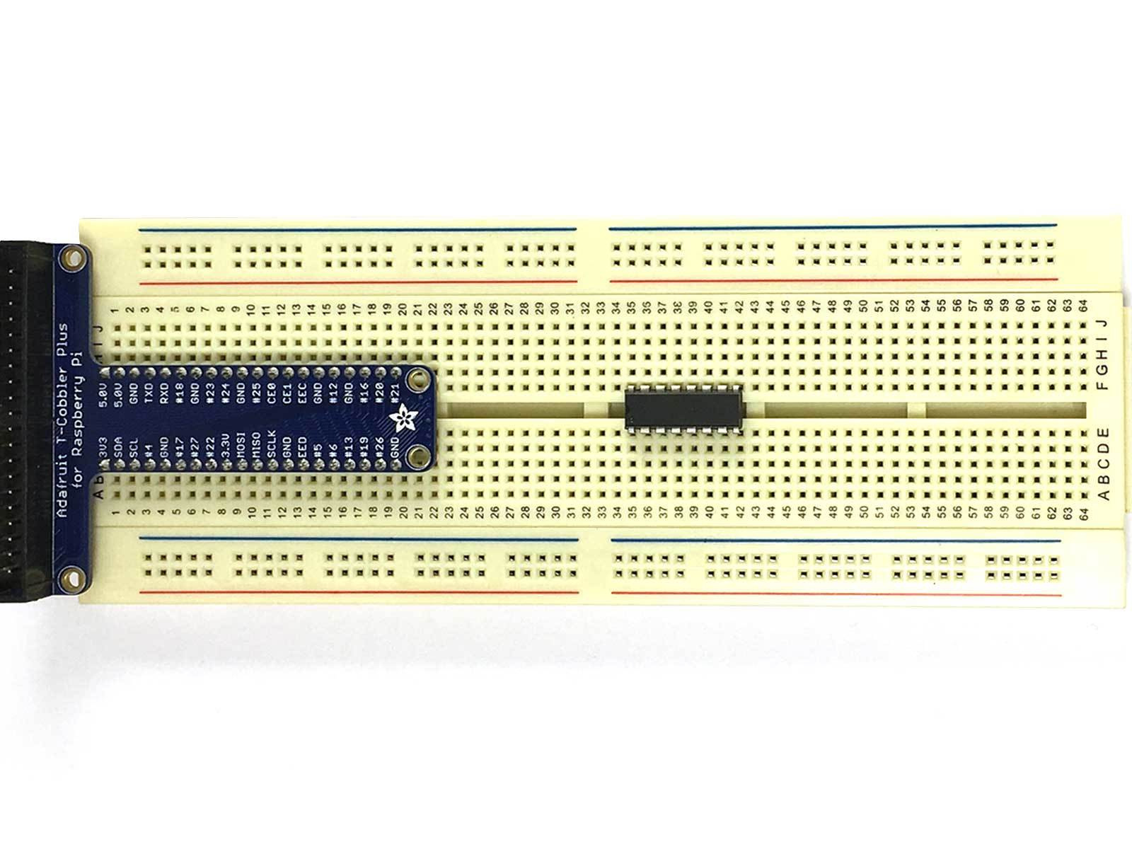
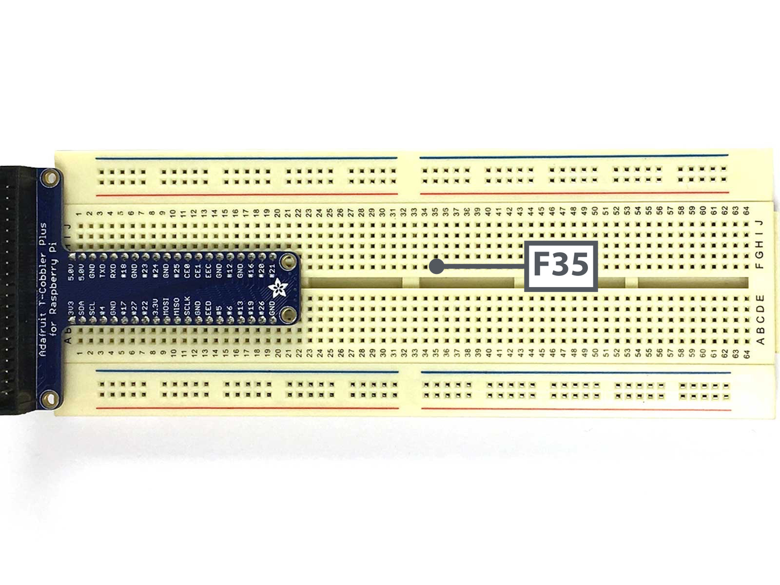
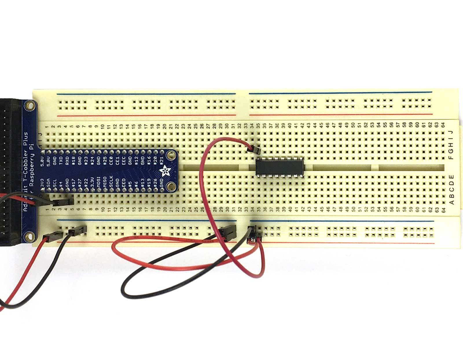
Connect MCP3008 to the breadboard. So that one side is between B35 to B42
The other side should be between F35 to F42
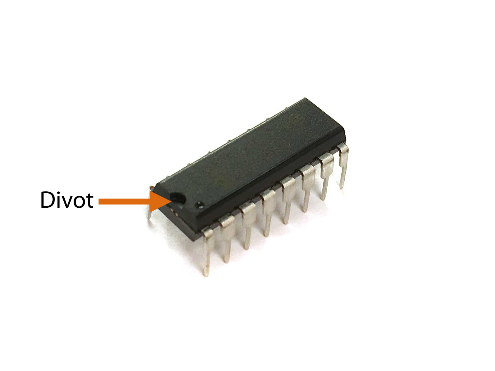
Note: The orientation of the MCP3008 matters here! Make sure that the divot, the little half circle indentation and dot on the MCP3008 is at B35 and F35.


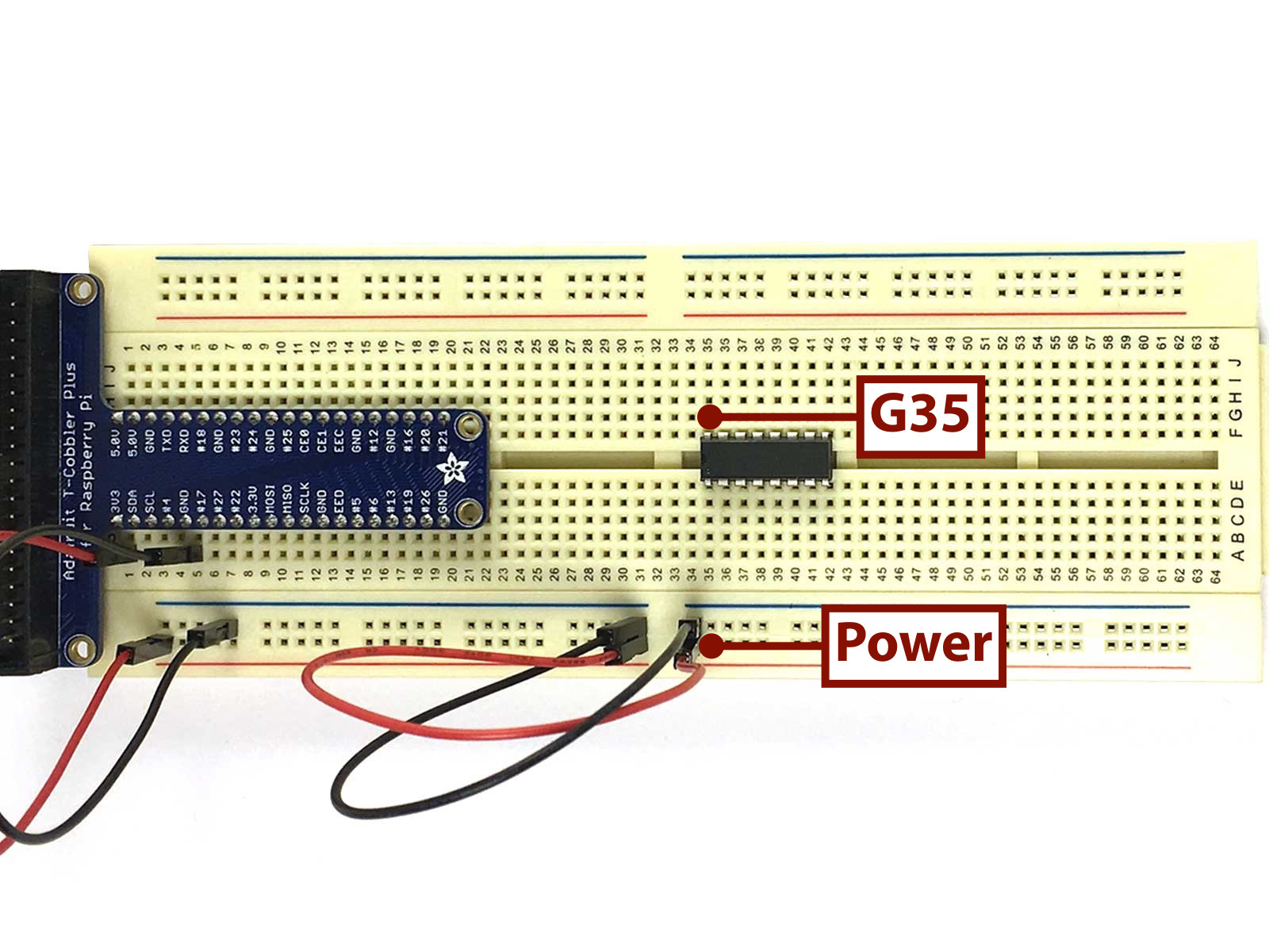
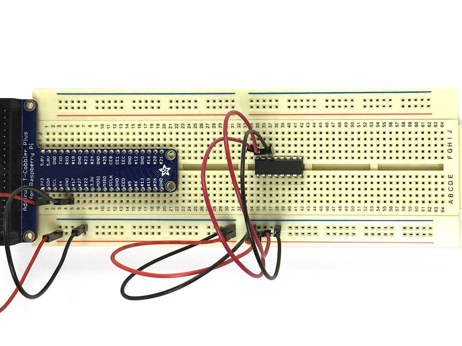
Run a Red Jumper Wire from G35 to the Power Rail to connect the MCP3008's VDD to power.
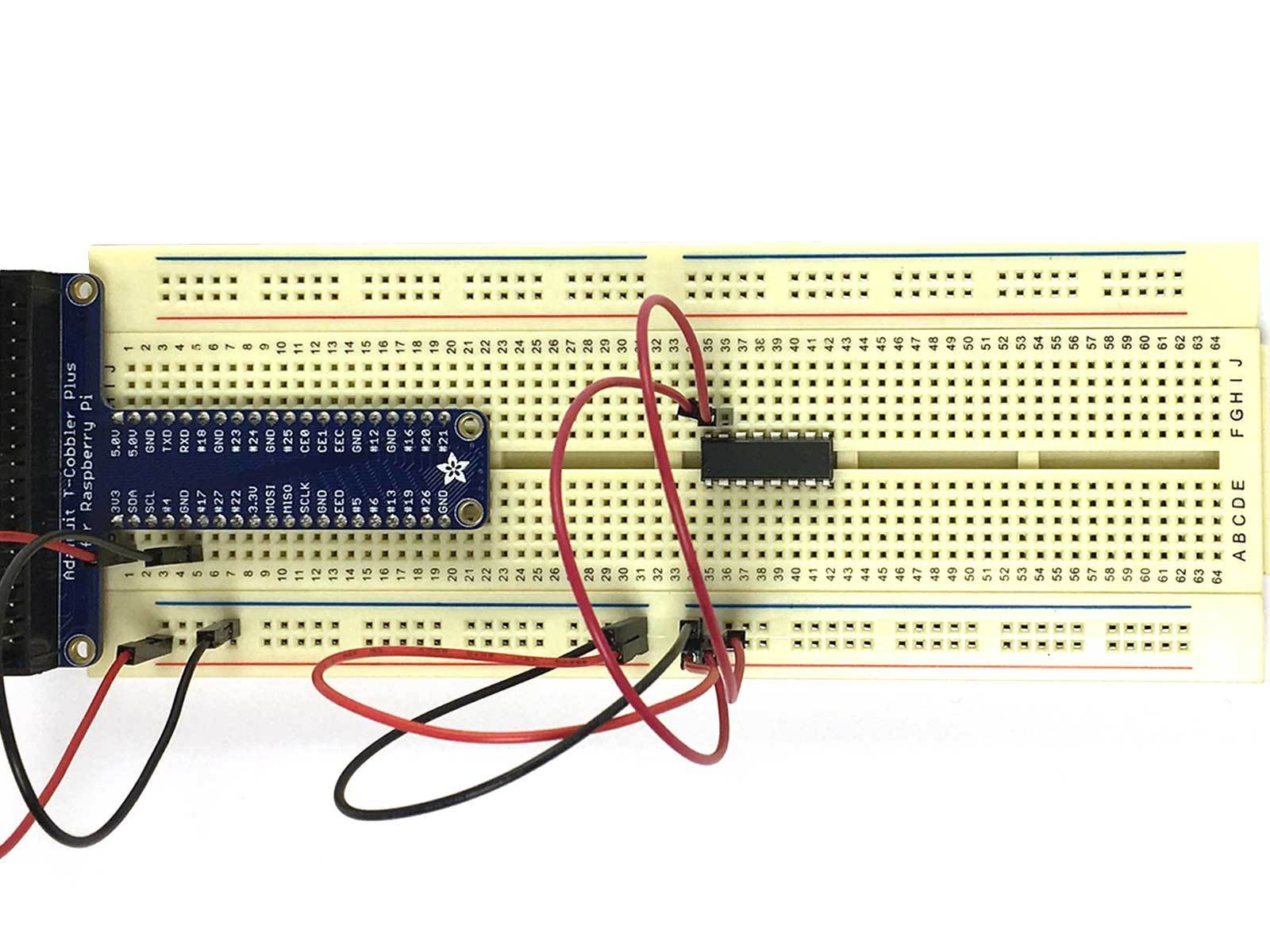
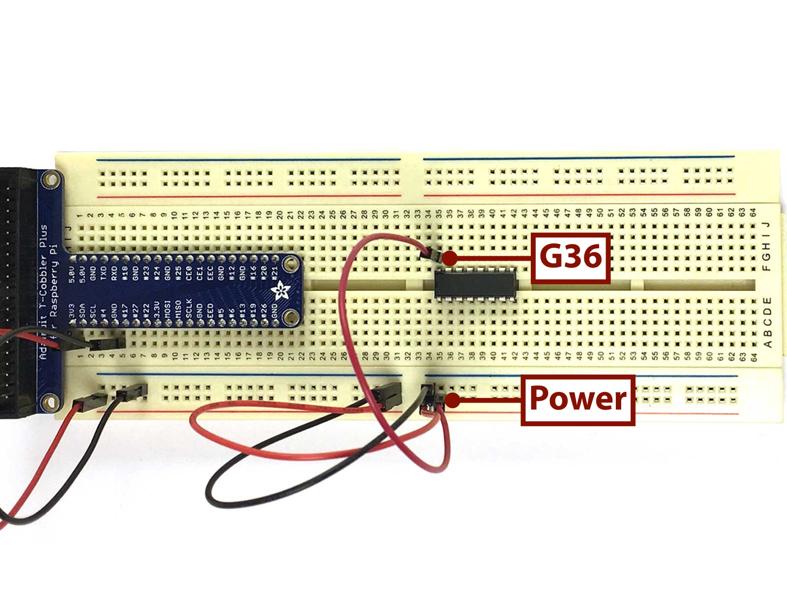
Run a Red Jumper Wire from G36 to the Power Rail to connect the MCP3008's VREF to power.
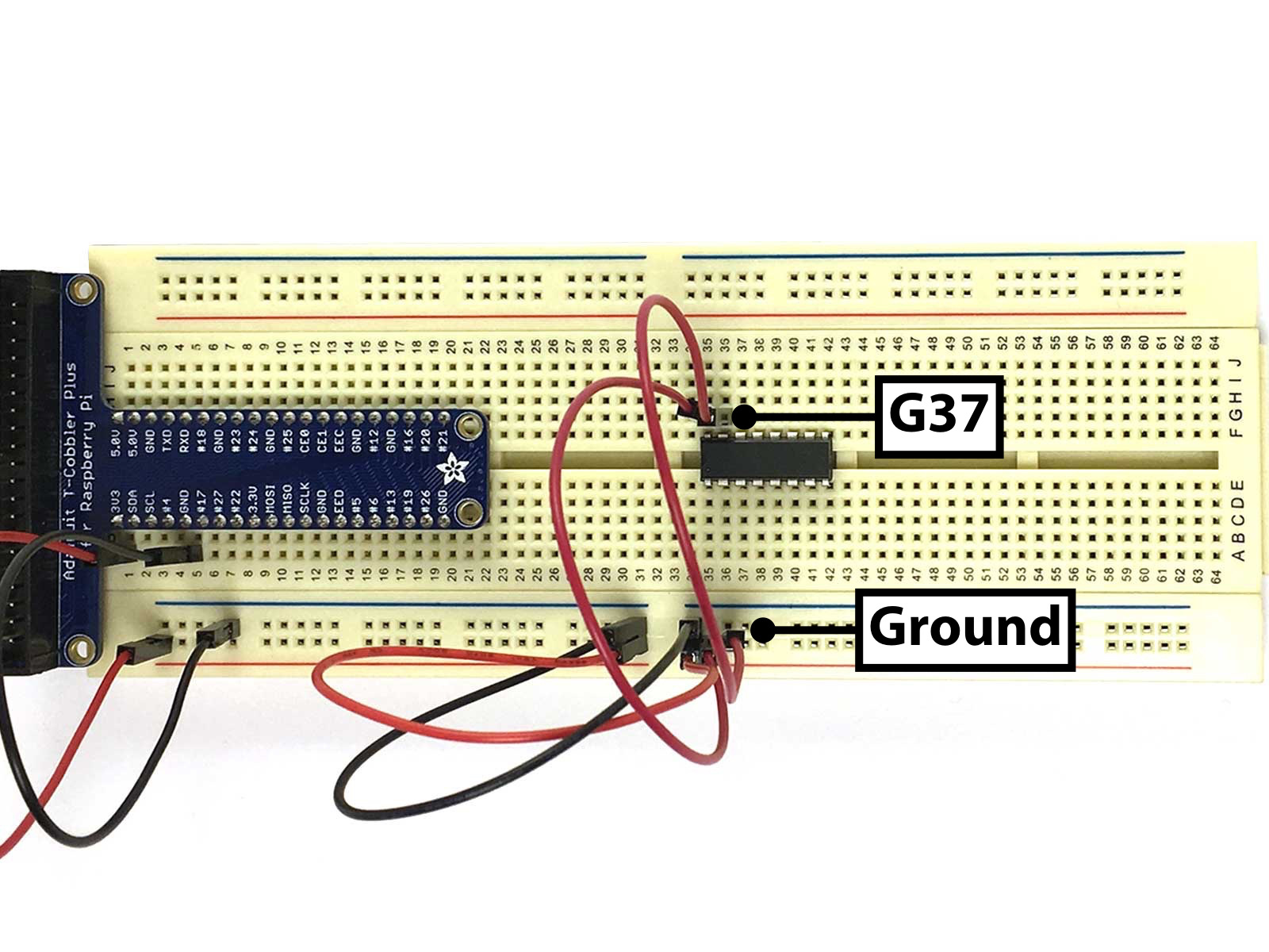
Run a Black Jumper Wire from G37 to the Ground Rail to connect the MCP3008's Analogue Ground to Ground.
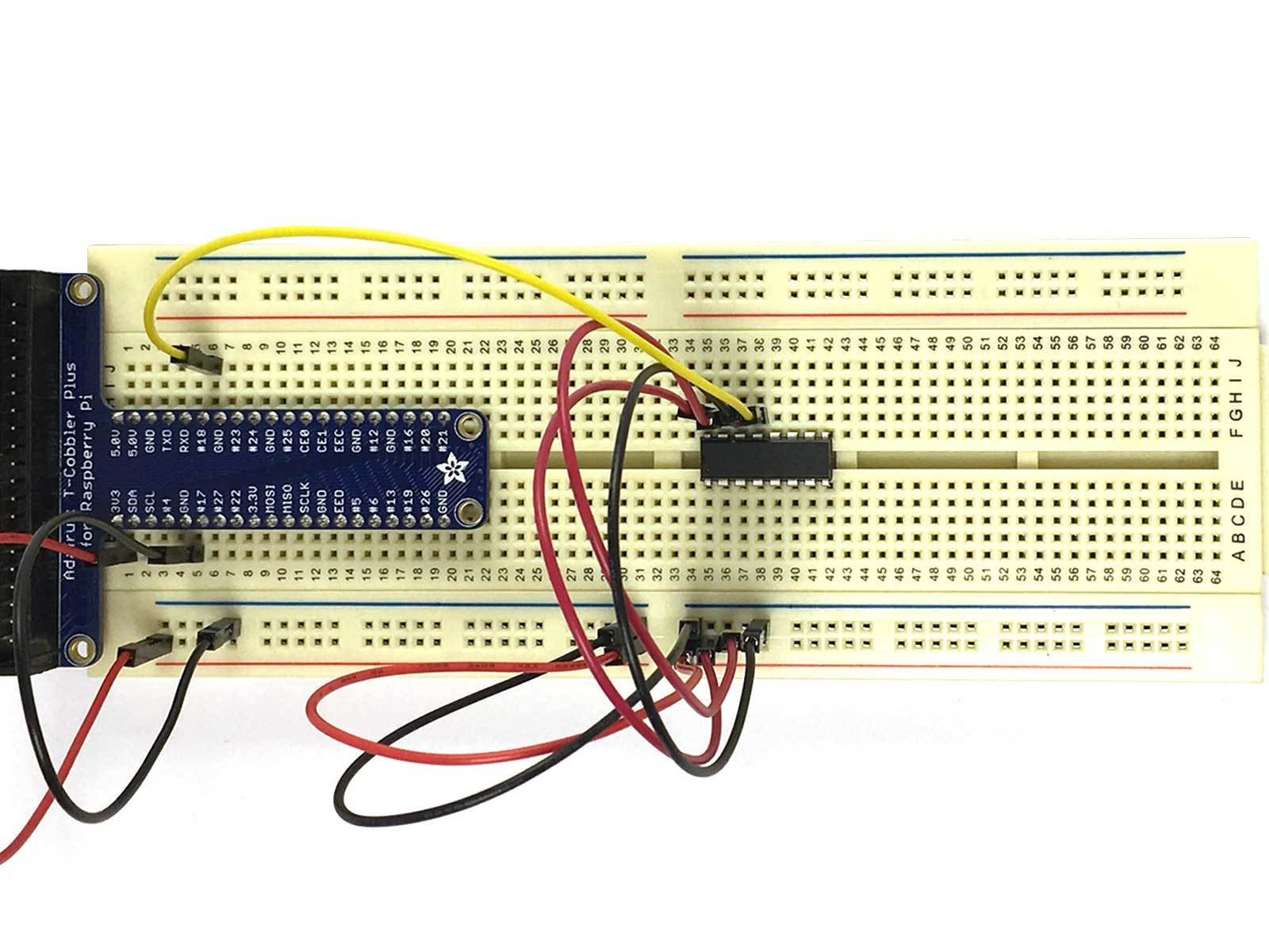
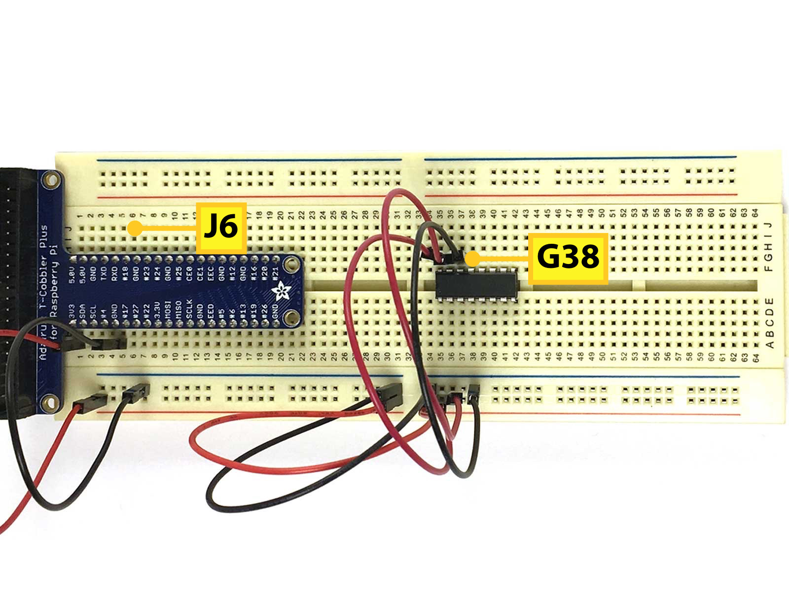
Run a Yellow Jumper Wire from G38 to J6 to connect the MCP3008's CLK to GPIO18.
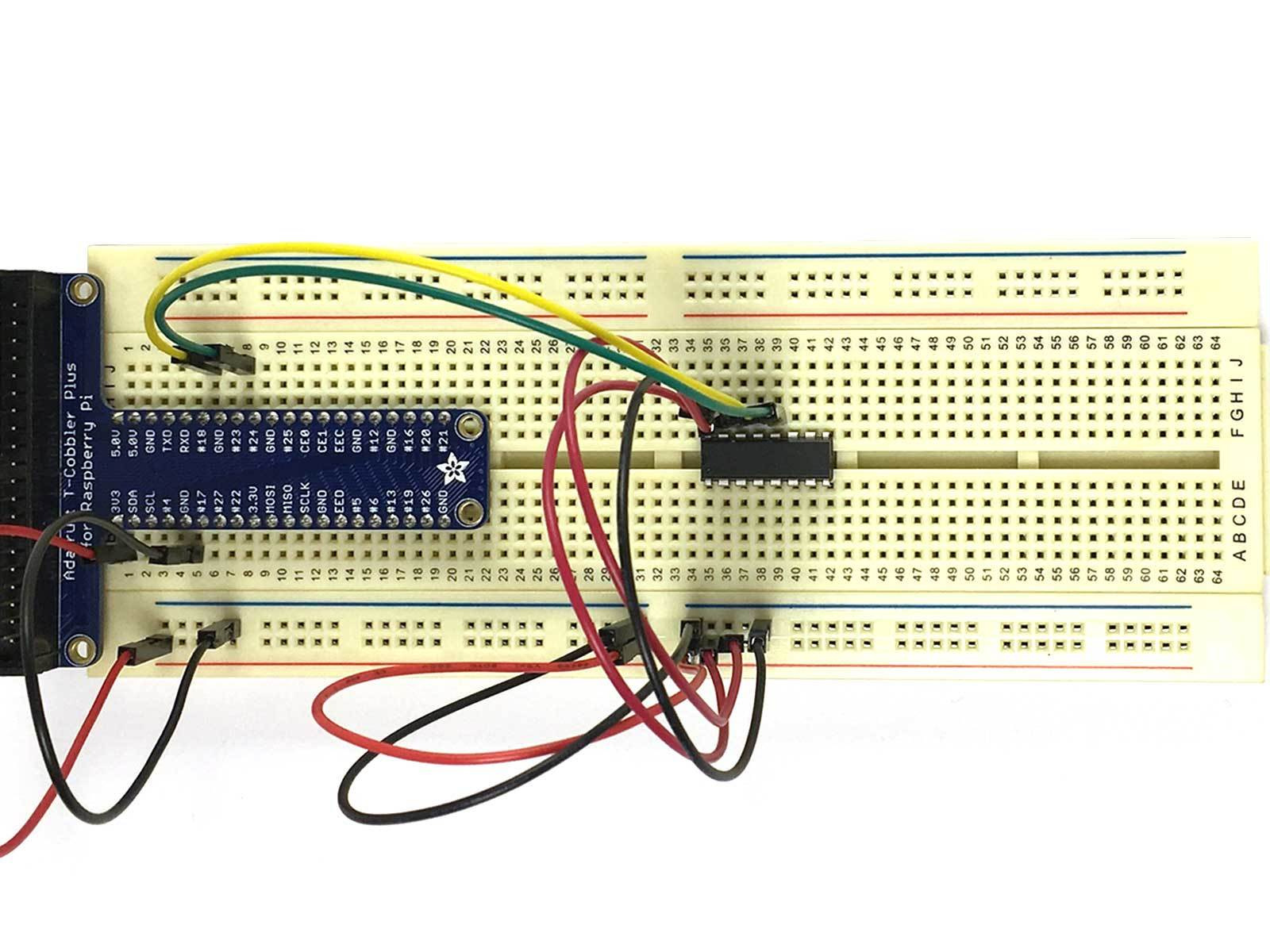
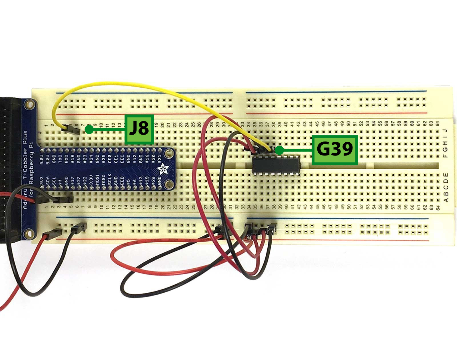
Run a Green Jumper Wire from G39 to J8 to connect the MCP3008's Digital Out to GPIO23.
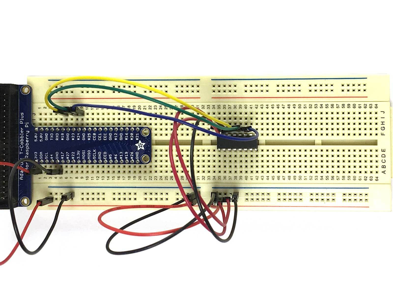
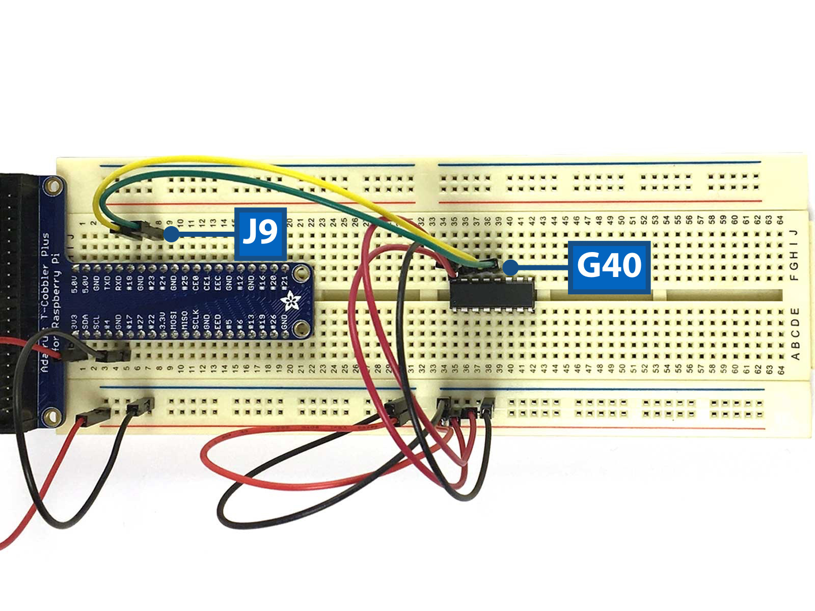
Run a Blue Jumper Wire from G40 to J9 to connect the MCP3008's Digital In to GPIO24.
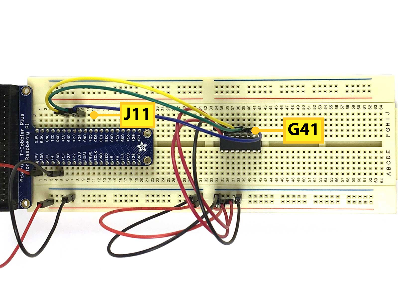
Run another Yellow Jumper Wire from G41 to J11 to connect the MCP3008's CS/SHDN to GPIO25.
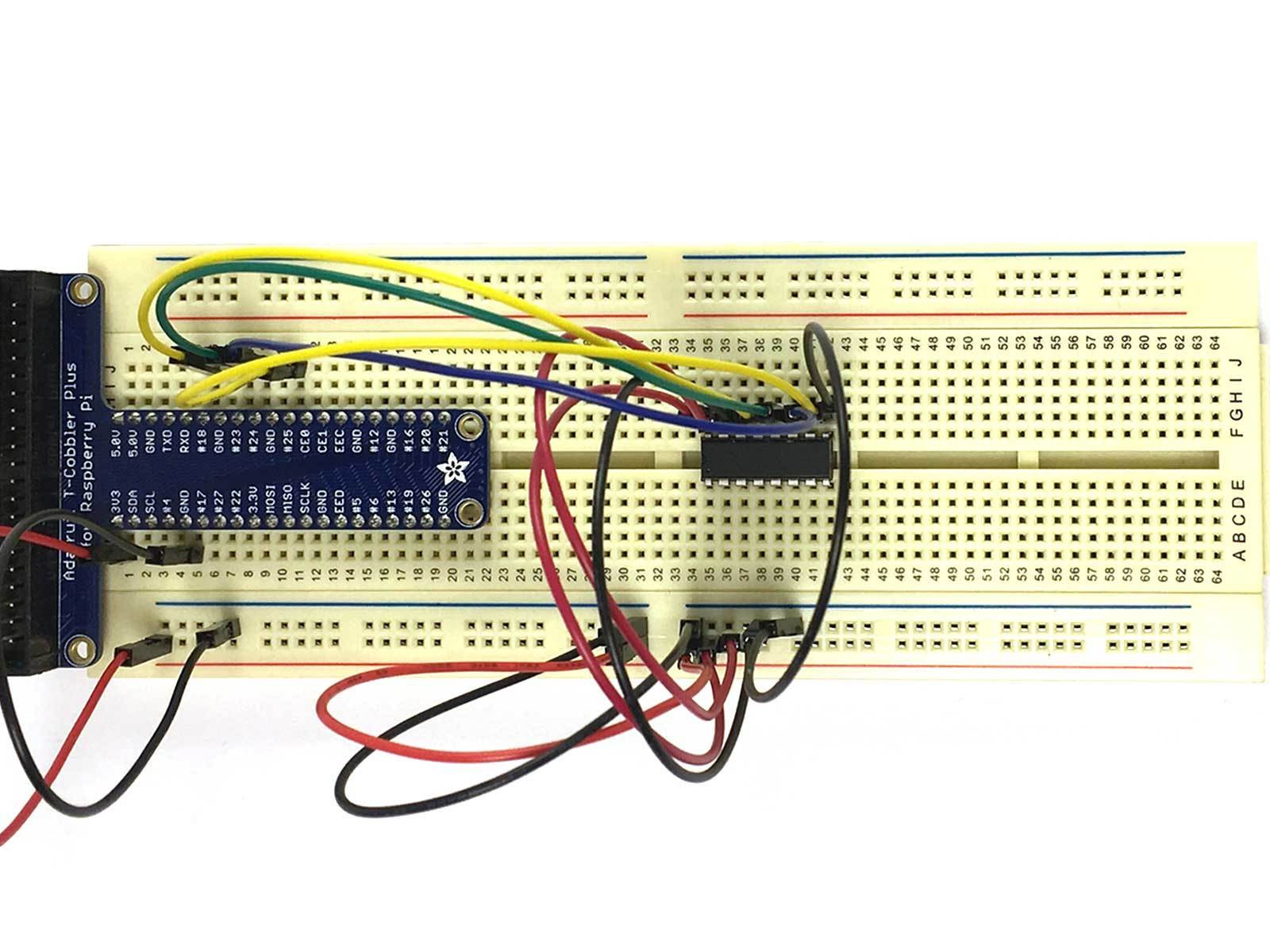
Run a Black Jumper Wire from G42 to the Ground Rail to connect the MCP3008's Digital Ground to Ground.


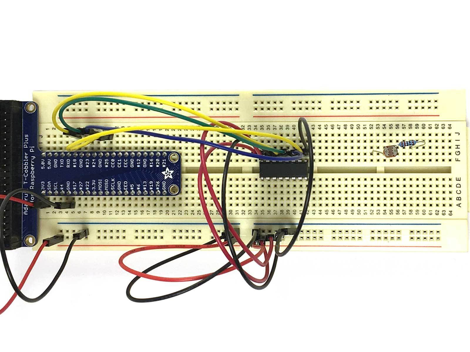
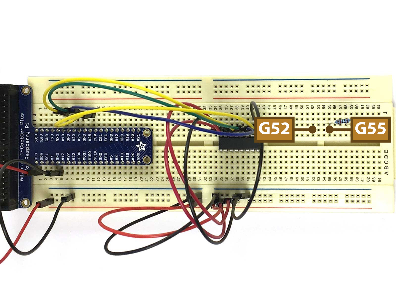
Insert a 10K Ohm Photo Resistor with one leg in G52 and the other in G55.
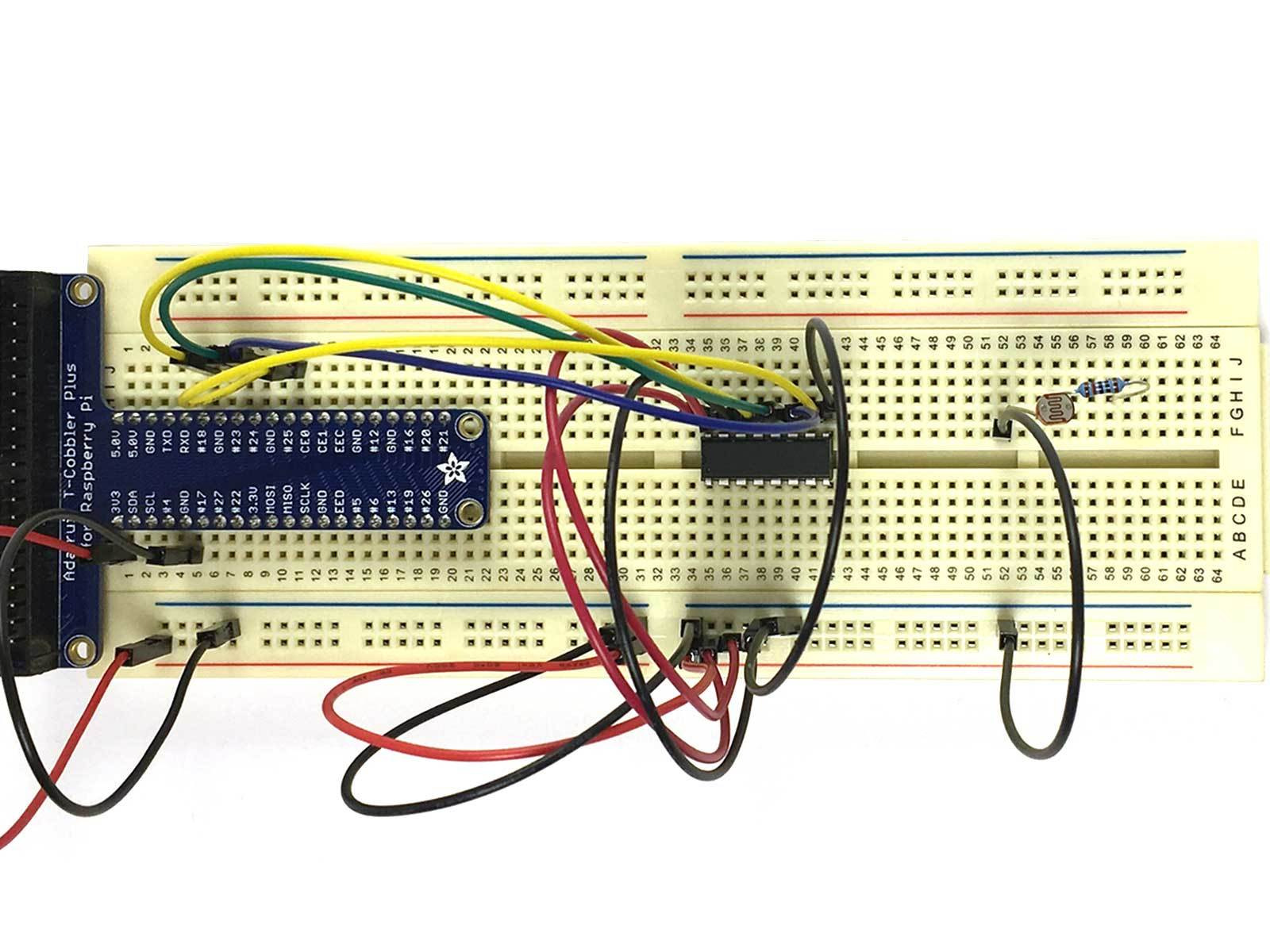
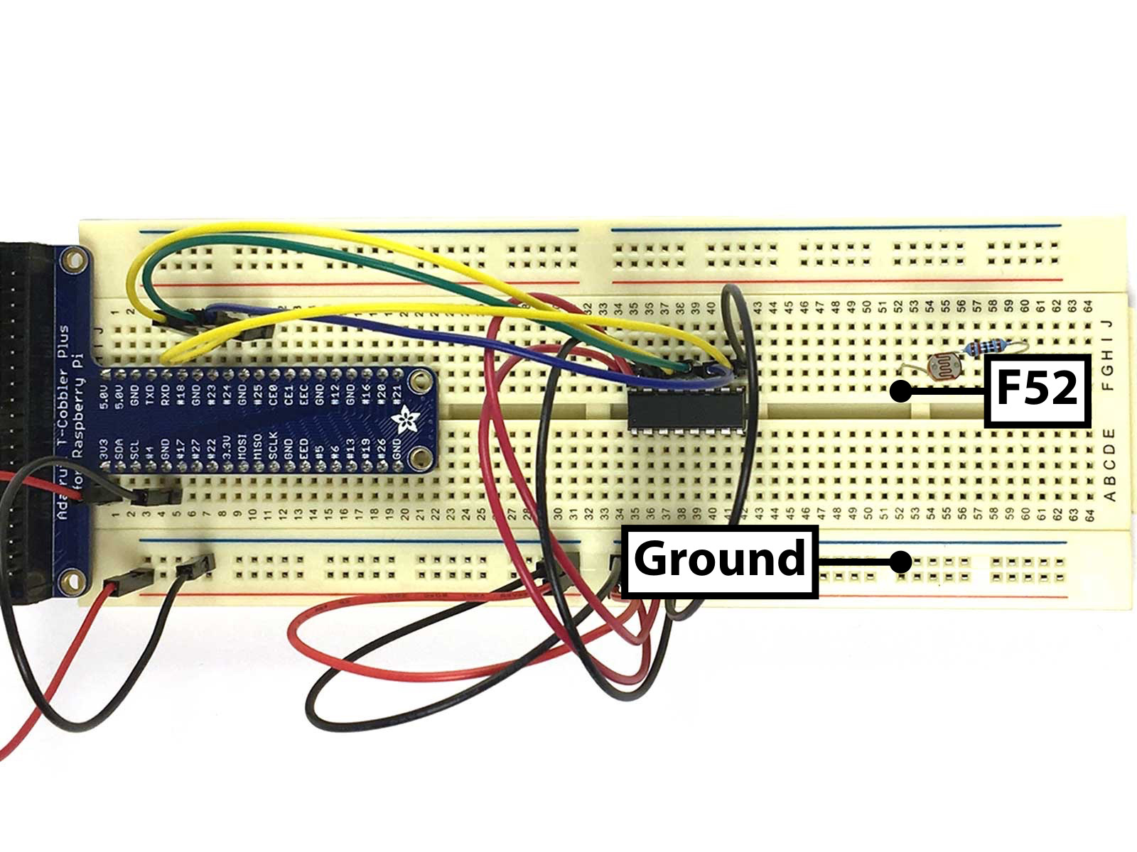
Run a Black Jumper between F52 and Ground to connect the Photo Resistor to Ground.
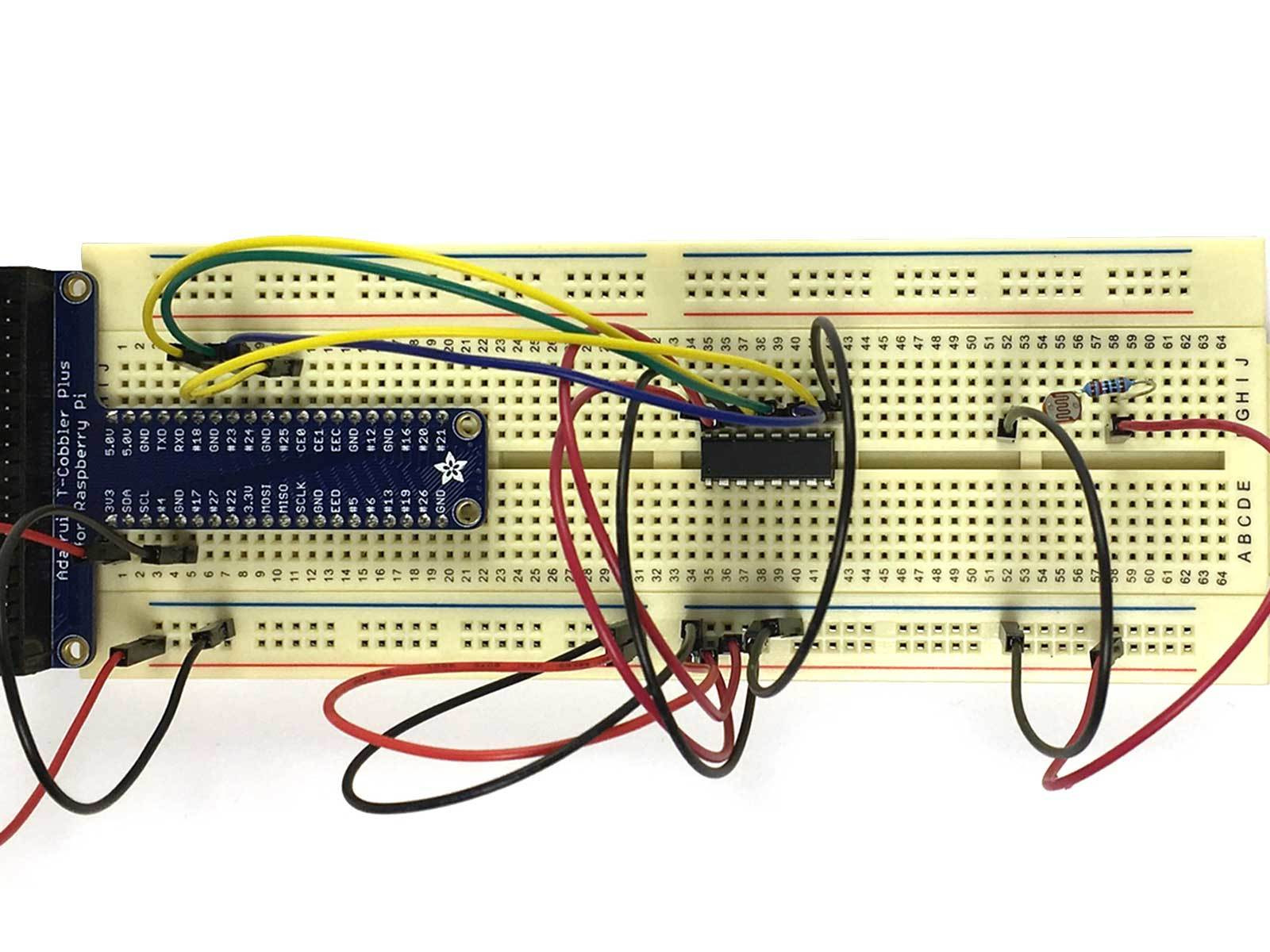
Run a Red Jumper between F58 and Power to connect the Resistor to the Power Rail.
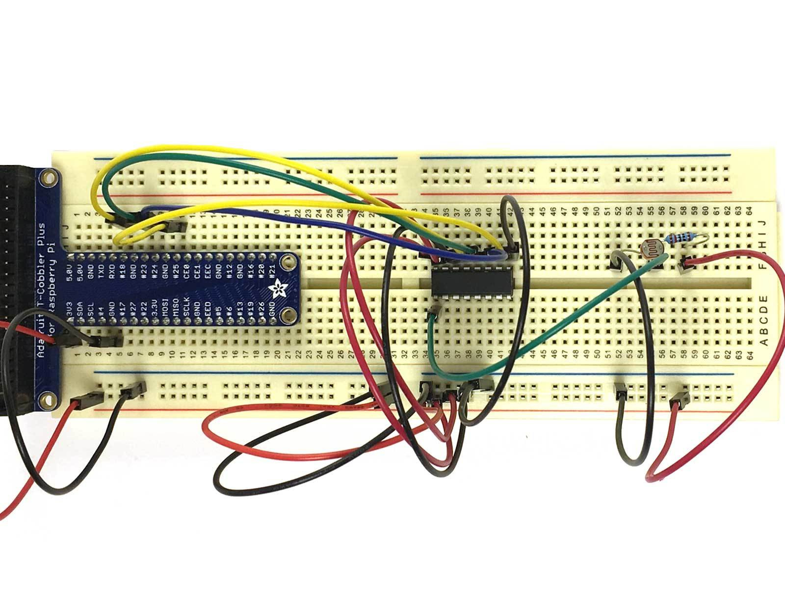
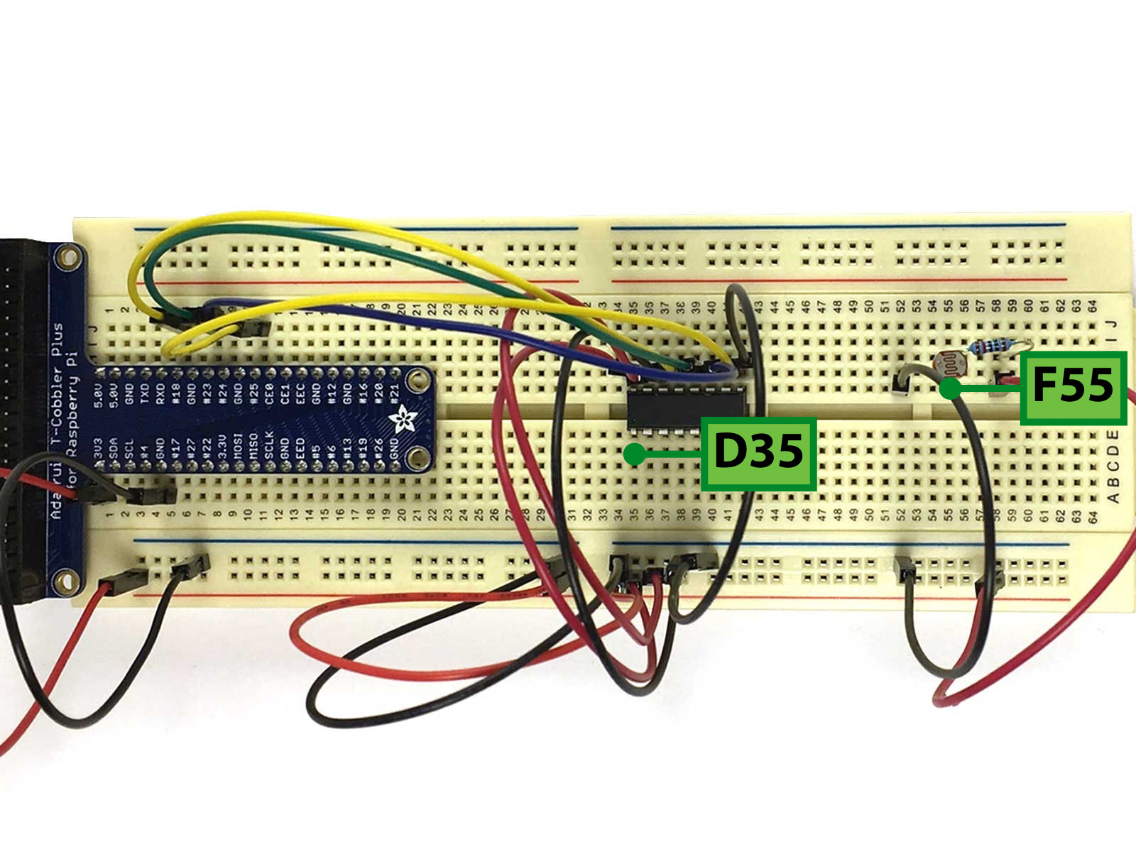
Run a Green Jumper between F55 and D35 to connect the Voltage Divider to Analogue Channel 0 of the MCP3008.
With a NOOBS microSD card, start up your Raspberry Pi and install Raspbian. Please follow our previous guide on doing just that if you are unsure how to. Alternatively, you could create your own NOOBS microSD card.
Now that the Raspberry Pi is connected to the Analogue to Digital Converter and light dependent resistor, we will program it. Let's install GPIO Zero, a Python library which builds upon existing GPIO libraries such as RPI.GPIO, rPIO, and pigpio. It helps to simplify the process by reducing boilerplate code.
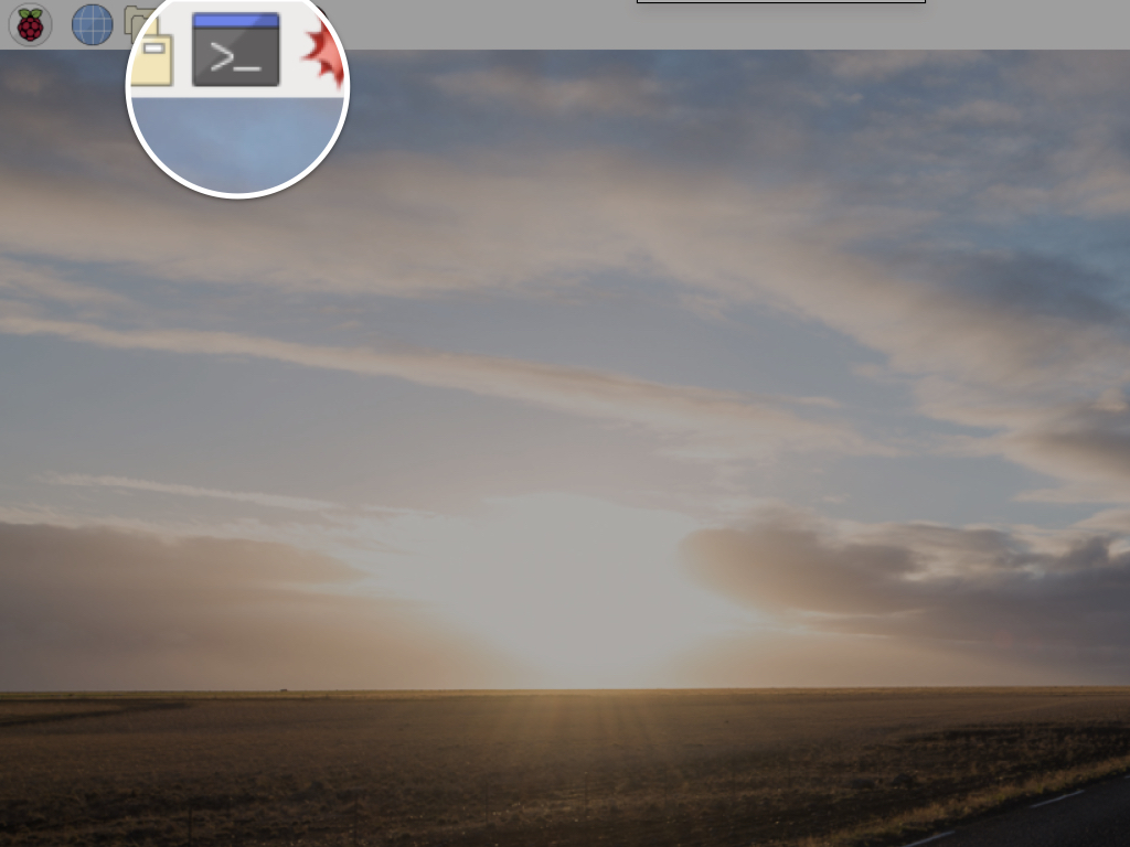
First, open a terminal window by clicking on the terminal icon on the top left hand corner.
First, open a terminal window by clicking on the terminal icon on the top left hand corner.
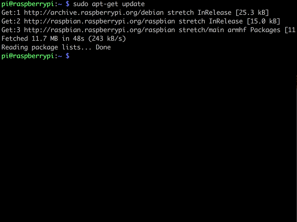
Type the following: sudo apt-get update
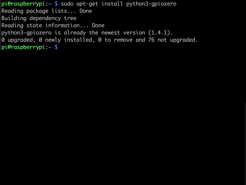
Install GPIO Zero library using: sudo apt-get install python3-gpiozero
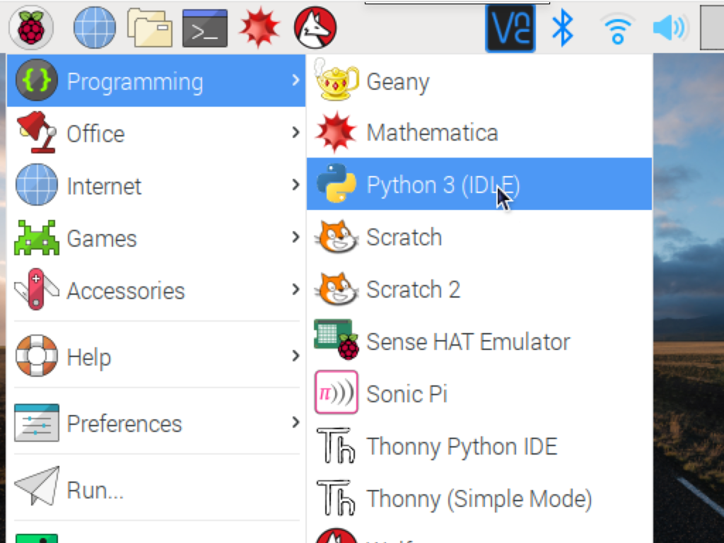
Click on the Raspberry Pi icon on the top left hand corner to access the main menu.
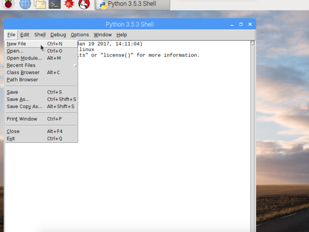
Click on Programming > Python 3 (IDLE).
Create a new file by clicking File > New File.
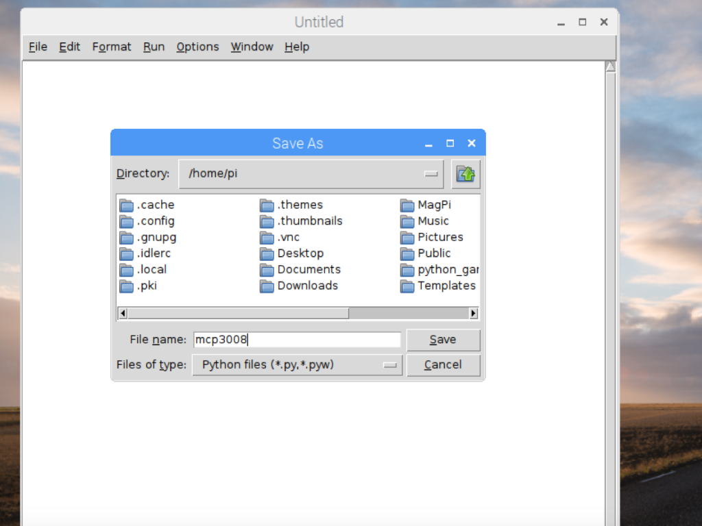
Next, save the file by clicking File > Save, and naming it mcp3008.py
from gpiozero import MCP3008
from time import sleep

ldr = MCP3008(channel=0, clock_pin=18, mosi_pin=24, miso_pin=23, select_pin=25)

while True:
    print(ldr.value)
    sleep(0.5)
Copy and paste the following code.
Save the mcp3008.py file
Note: The gpiozero library provides two SPI implementations, a software based implementation or a hardware based implementation. So the MCP3008 can be connected to the Raspberry Pi either with the hardware SPI bus, or with any four GPIO pins and software SPI to communicate to the MCP3008. In this guide, we've chose to use software SPI.
If you want to try using hardware SPI, make sure the connections are:
VDD (Pin 16) wire this to 3.3V
VREF (Pin 15) wire this to 3.3V
AGND (Pin 14) wire this to ground
CLK (Pin 13) wire this to GPIO11 (Pin 23/SCLK)
DOUT (Pin 12) wire this to GPIO9 (Pin 21/MISO)
DIN (Pin 11) wire this to GPIO10 (Pin 19/MOSI)
CS (Pin 10) wire this to GPIO8 (Pin 24/CE0)
DGND (Pin 9) wire this to ground
Next, make sure SPI is enabled over in Raspberry Pi Configuration > Interfaces.
Then, swap the existing line of code with this instead:
ldr = MCP3008(channel=0, clock_pin=11, mosi_pin=10, miso_pin=9, select_pin=8)
