Digital Outputs with a Raspberry Pi
Learn to use GPIO Zero library to turn an LED on and off
Written By: Cherie Tan

Difficulty
Easy
Steps
11
One of the simplest ways to get started with physical computing is to get an LED to turn on and off.
In this guide, we will get an LED to blink by connecting it to a Raspberry Pi 3 Model B. We will then program it using the GPIO Zero Python library.
On completion of this guide, you will have gained a better understanding of digital outputs.
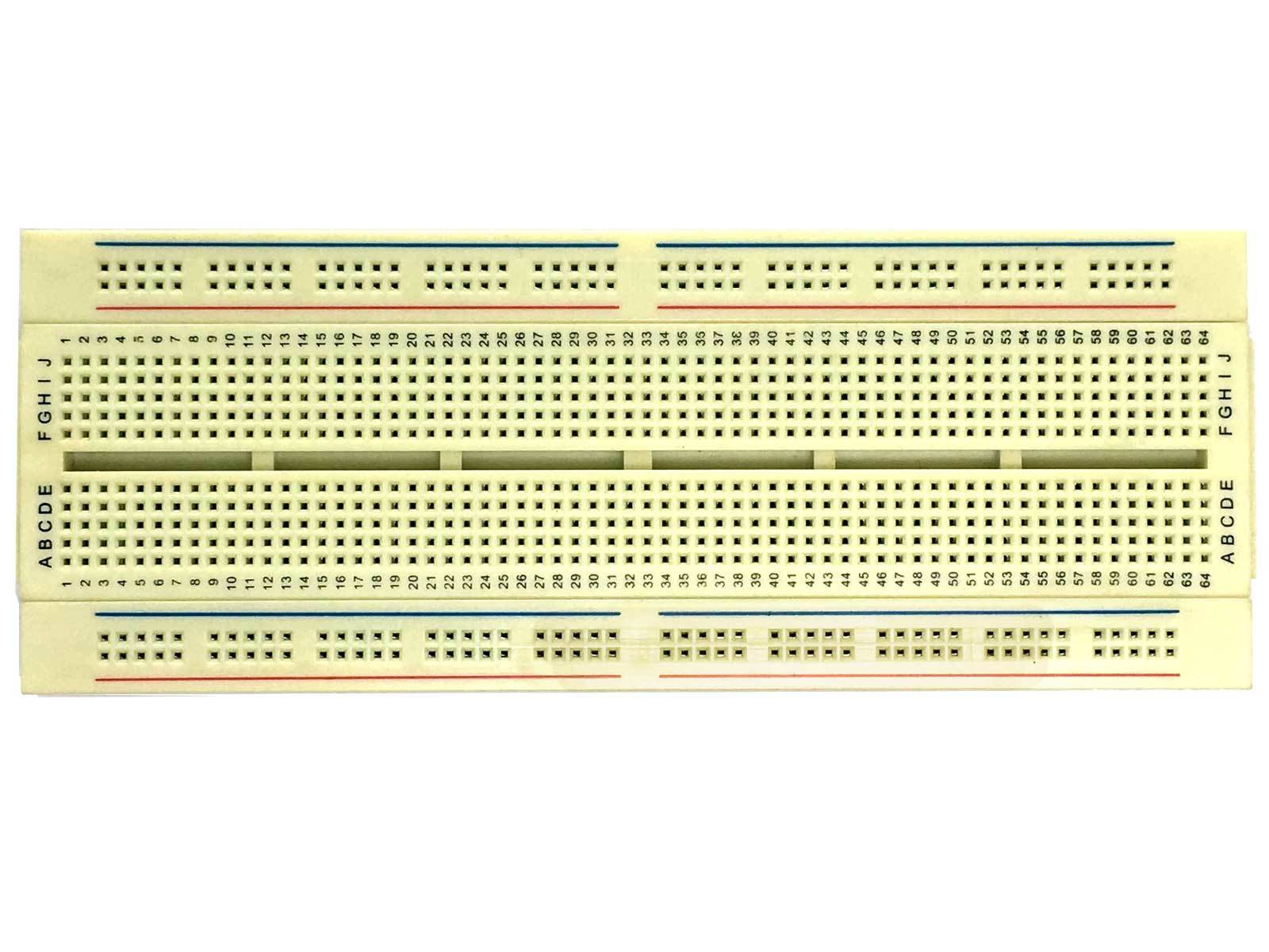
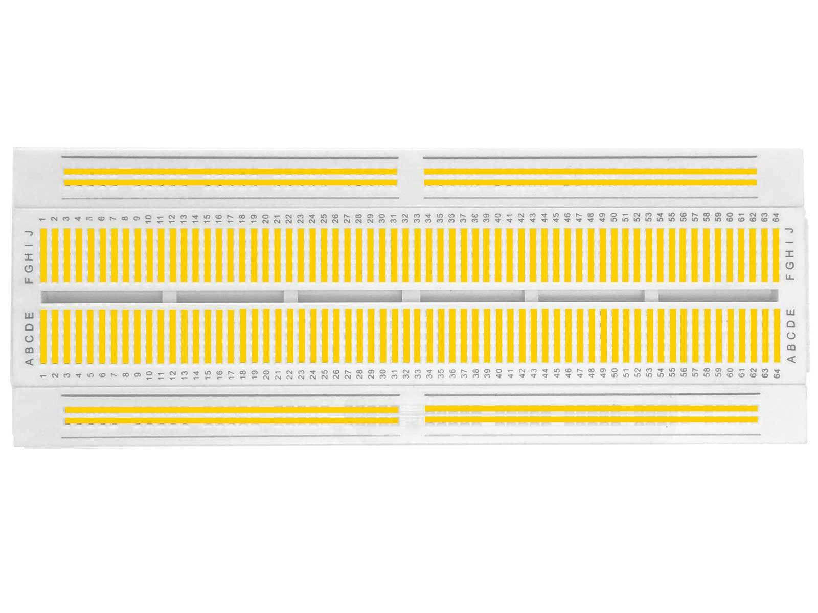
In this tutorial we're going to use a solderless breadboard for prototyping.
A modern solderless breadboard consists of a perforated block of plastic with conductive spring clips under the perforations.
The holes in the breadboard are sometimes called tie points.


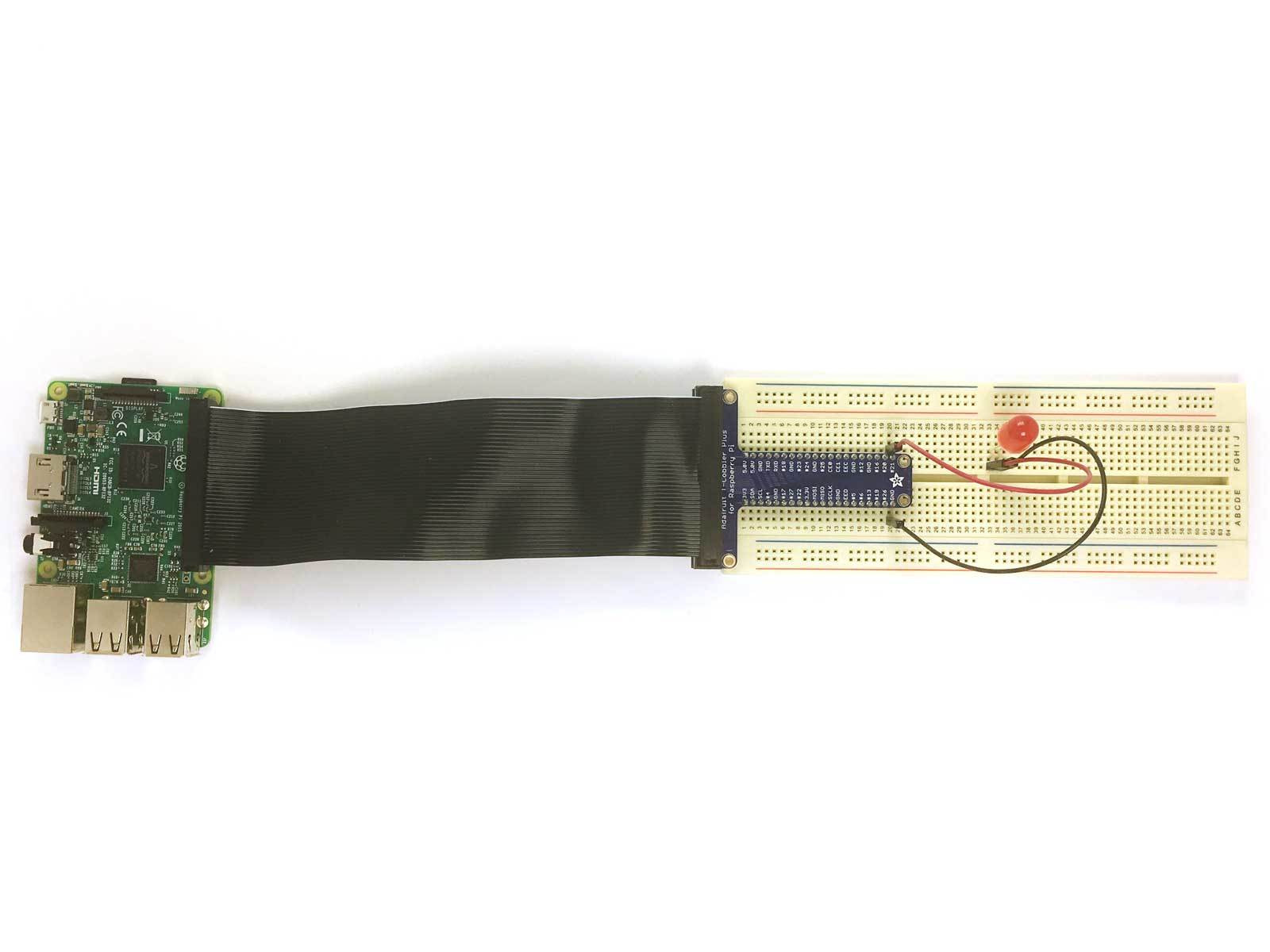
To connect our Raspberry Pi to our breadboard we're going to use a GPIO Breakout Board.
Take the Breakout Board and Ribbon Cable out of the packaging and discard the protective shipping foam.
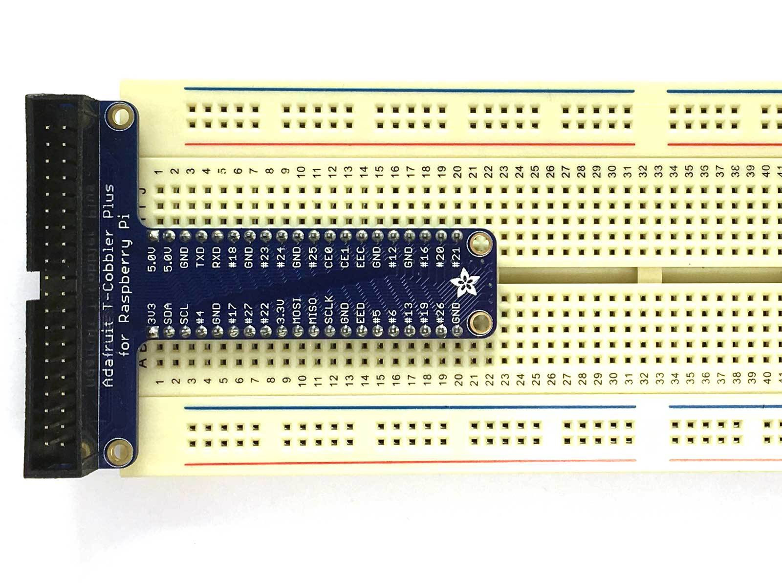
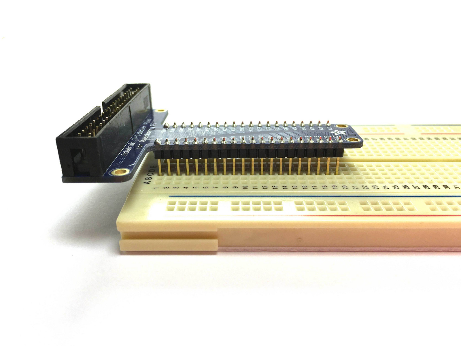
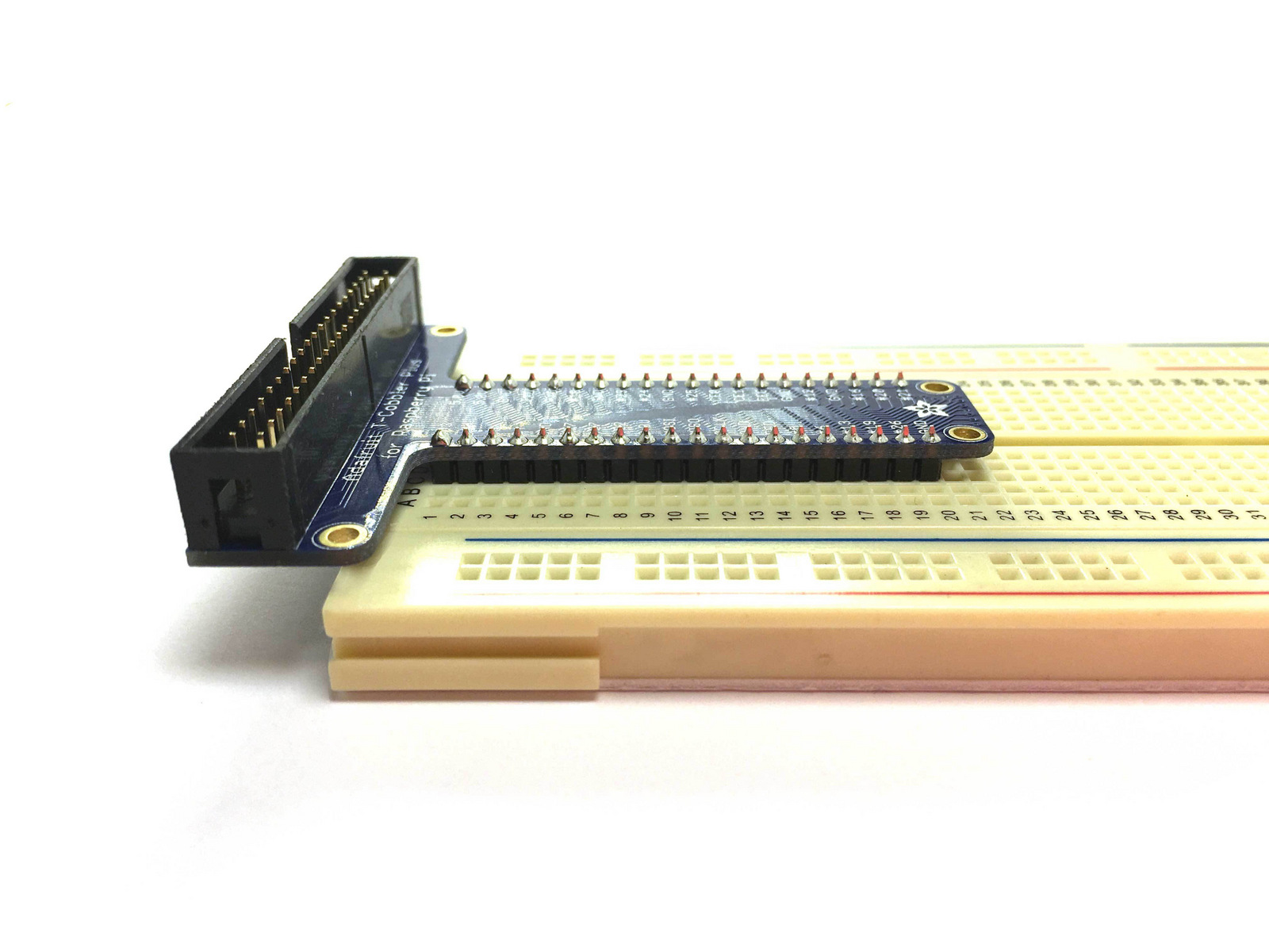
Insert the Breakout Board so that the top pins are aligned with Row 1 of the Breadboard.
Ensure that the Breakout Board is fully inserted into the Breadboard so that the pins make good contact. This will take some force.


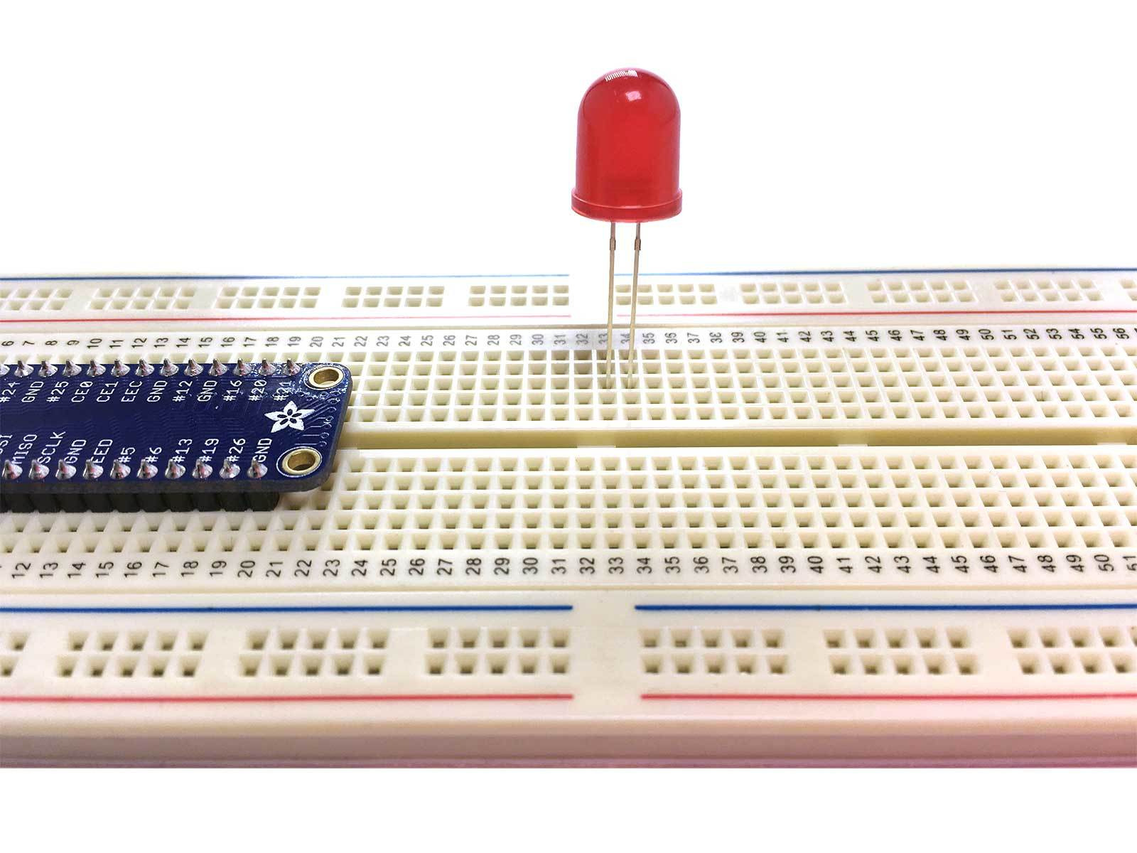
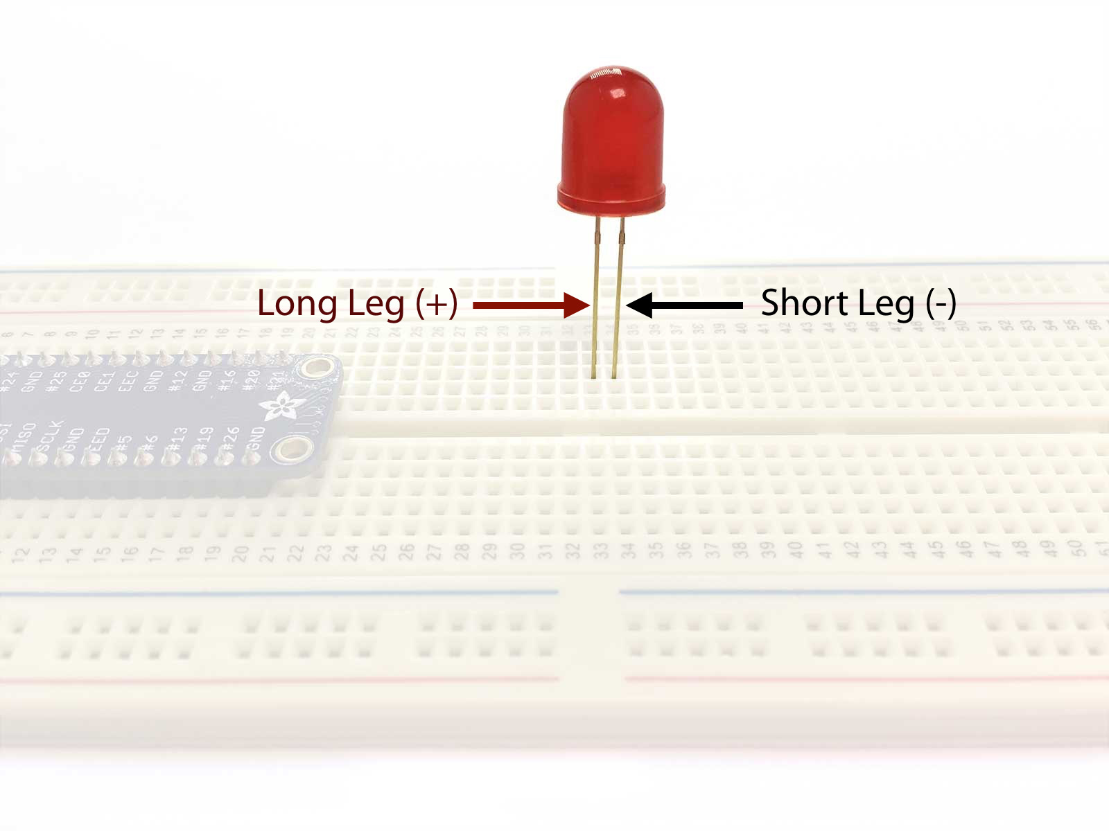
This is a light-emitting diode (LED).
When power is provided to the long leg (+), and the short leg (-) is connected to ground, current flows and light is emitted.
No current flows and no light is emitted if a small voltage is applied in the reverse direction
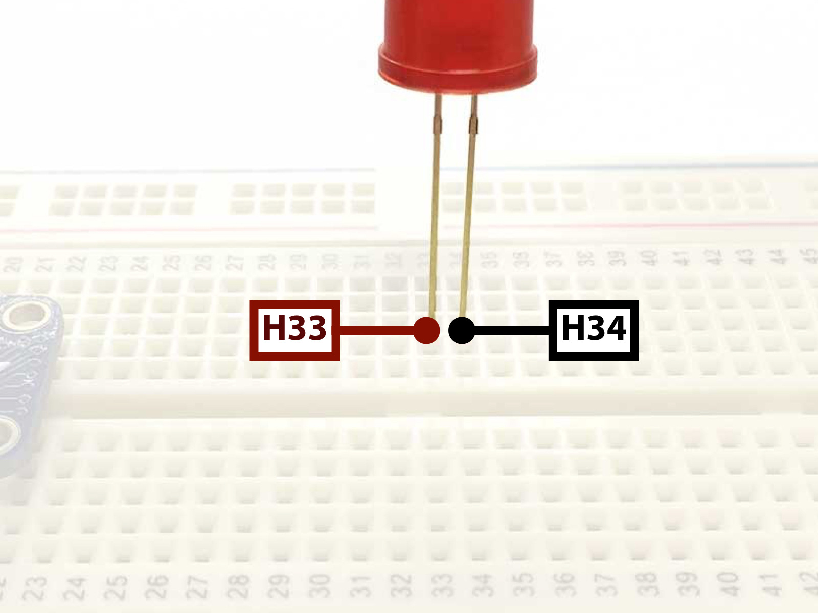
Insert the LED into the breadboard with the long leg in tie point H33 and the short leg in H34.
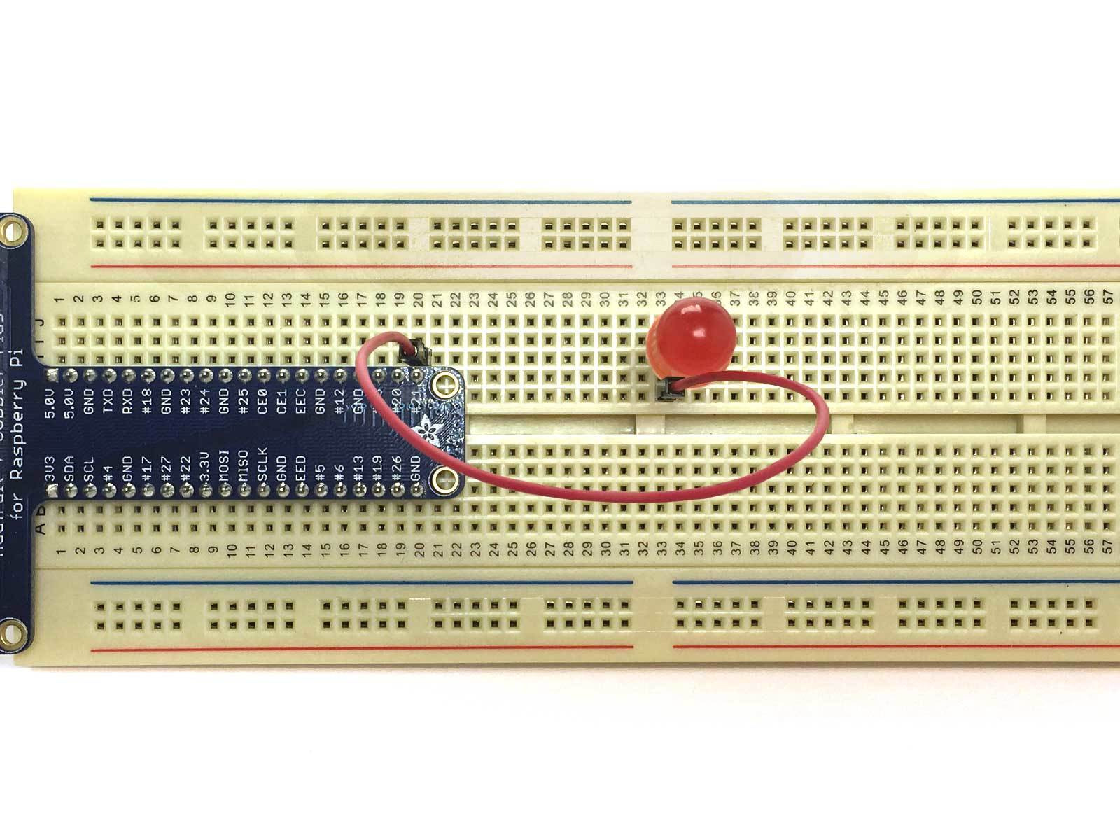
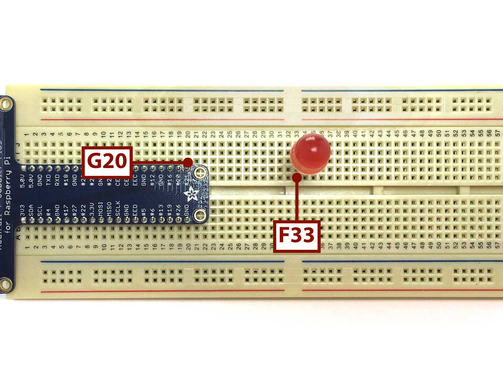
Connect a Red Jumperwire between tie point G20 (which is next to GPIO21) and F33.
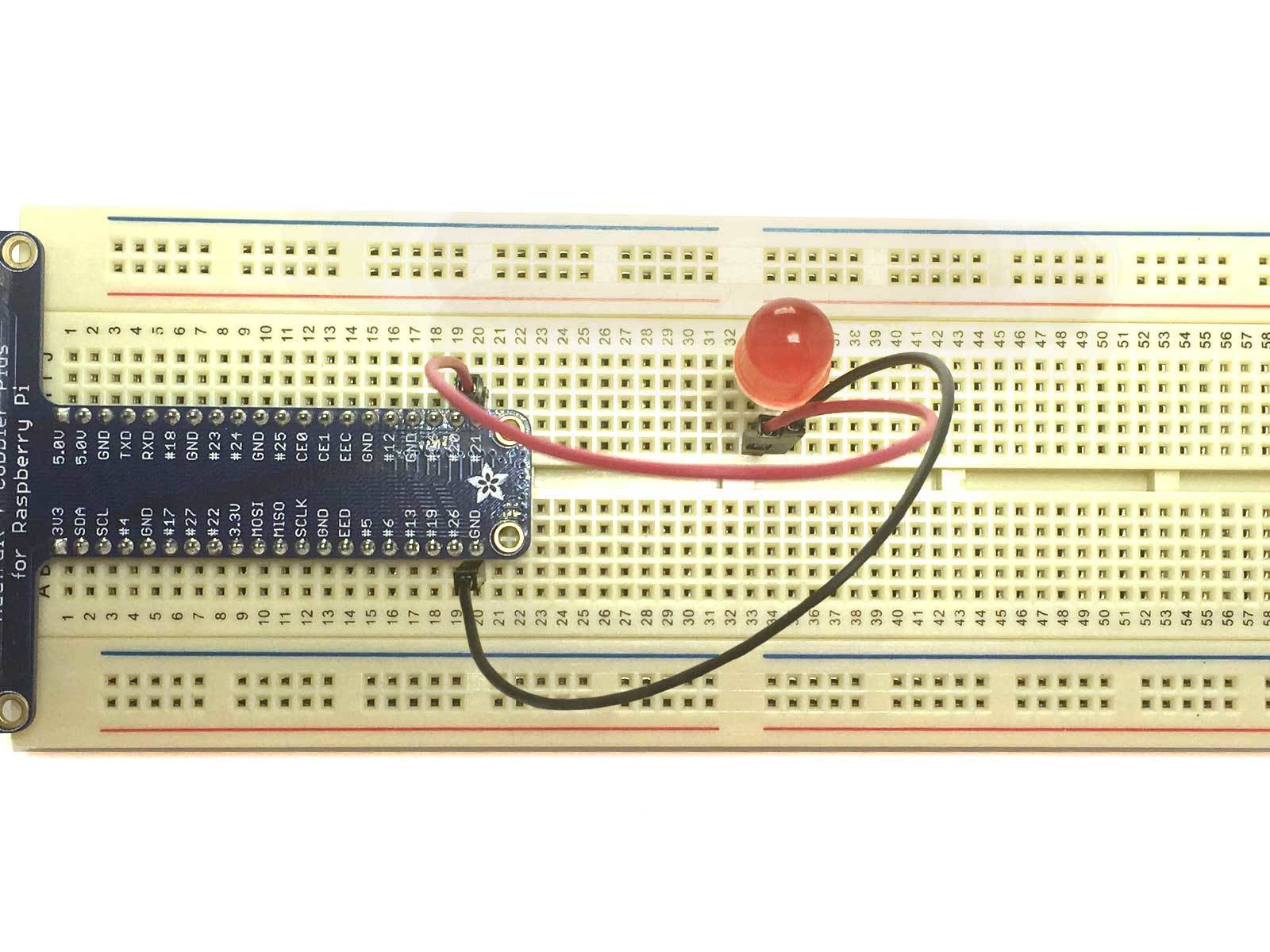
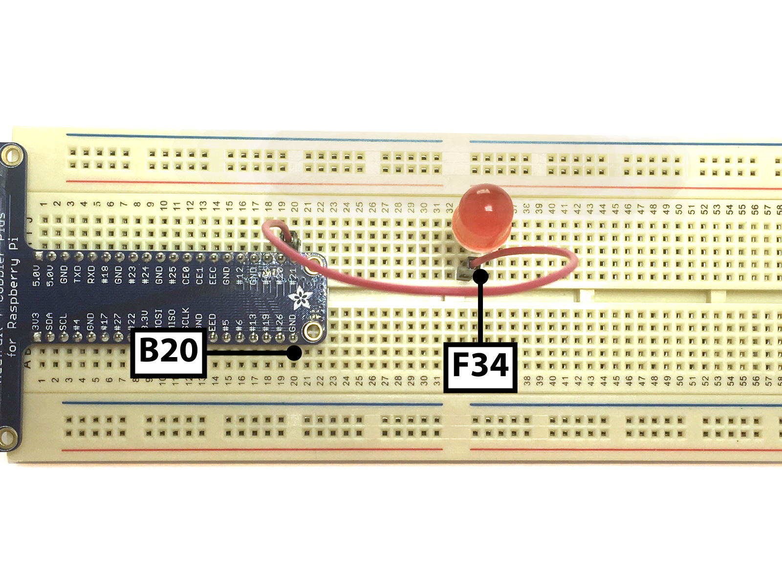
Connect a Black Jumperwire between tie point B20 (which is next to GND) and F34.
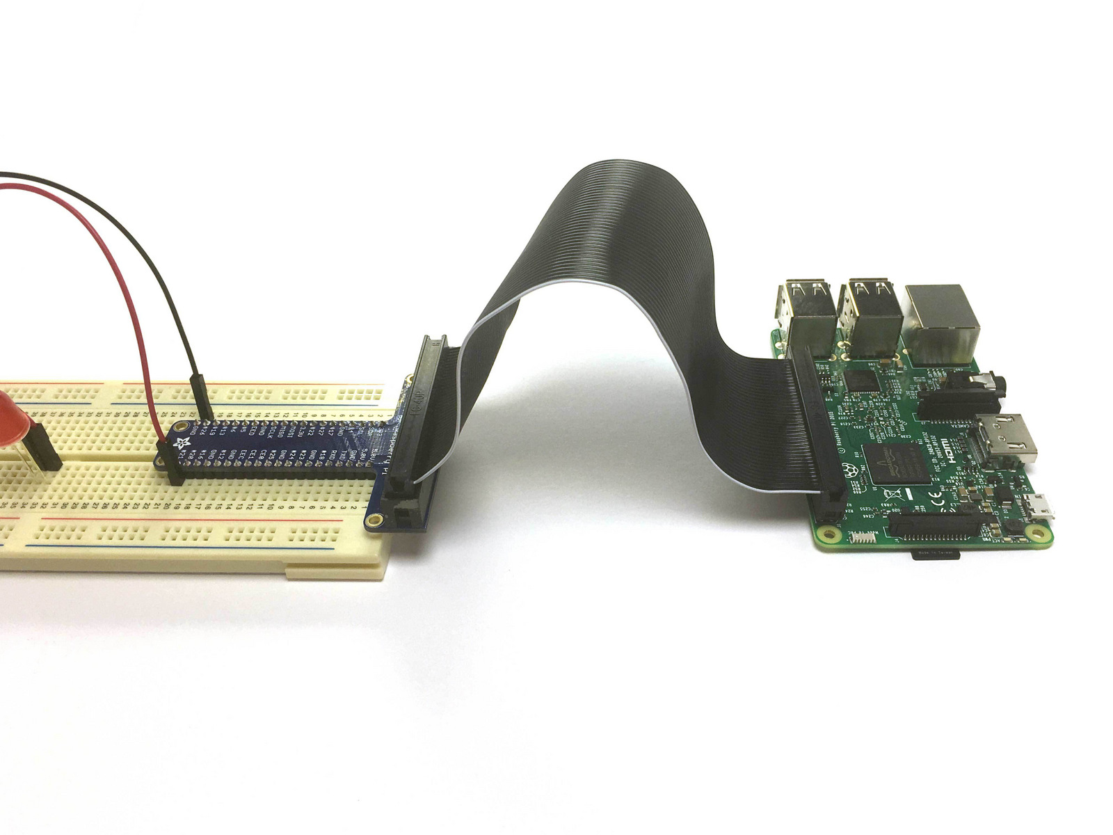
Insert the Ribbon Cable into the Breakout. A notch means you can really only insert it one way.
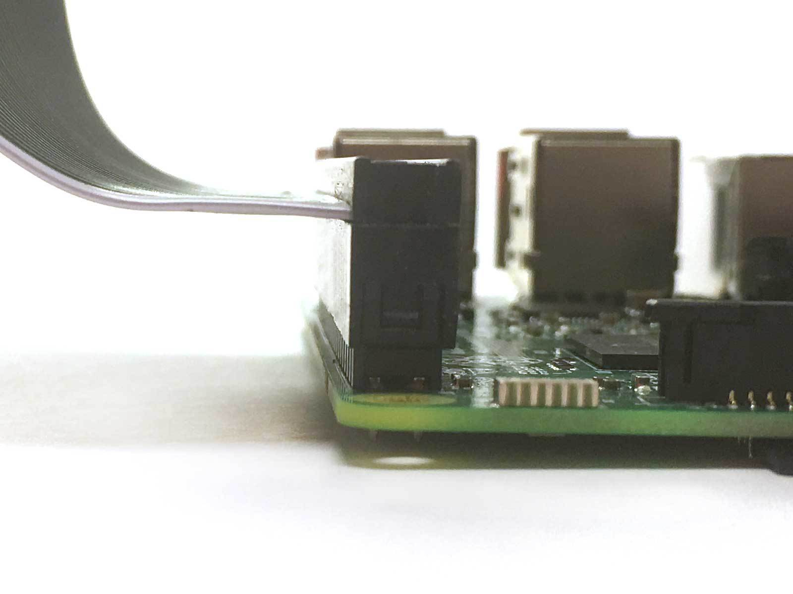
Connect the other end of the Ribbon Cable so that it does not fold, and the white line on the Ribbon Cable is closest to the SD Card Slot end of the Raspberry Pi.
Make sure that the Ribbon Cable is on both rows of GPIOs.
Now that we have the Raspberry Pi hooked up to the breadboard and LED, we will need to program it to turn the LED on and off. We will install GPIO Zero, a Python library which builds upon existing GPIO libraries such as RPI.GPIO, rPIO, and pigpio. It will simplify the process by reducing boilerplate code.
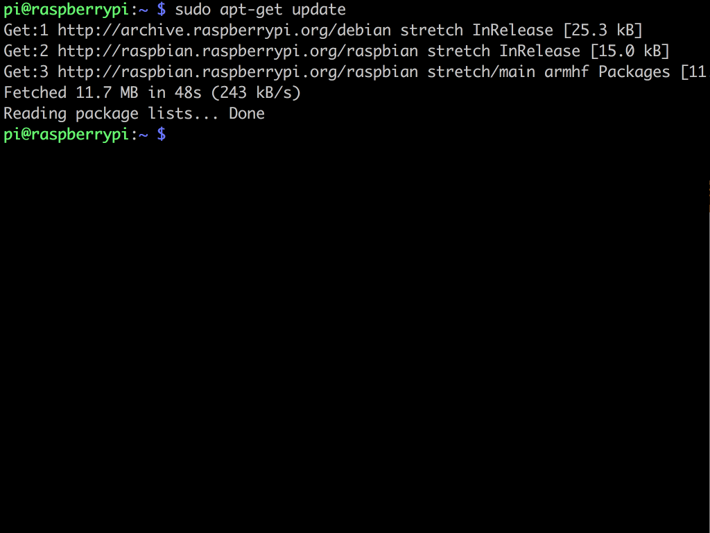
To do so, open a terminal window and enter the following: sudo apt-get update
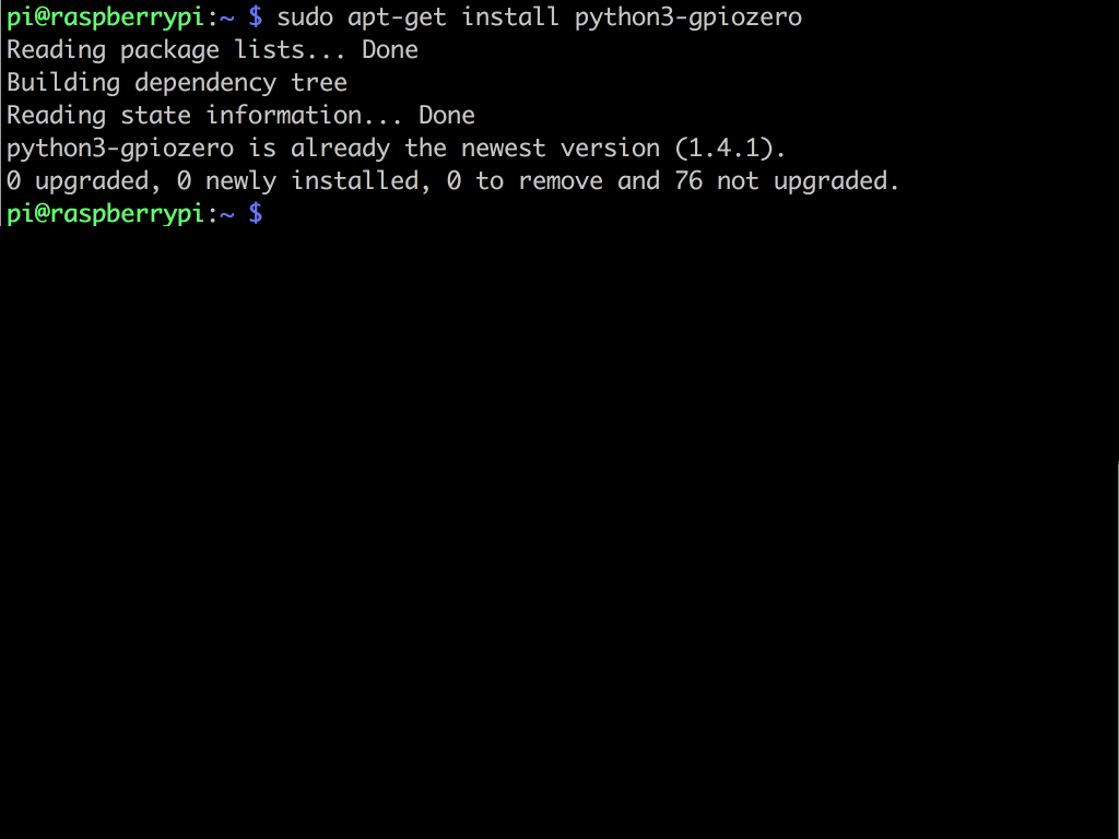
Then enter the following command: sudo apt-get install python3-gpiozero
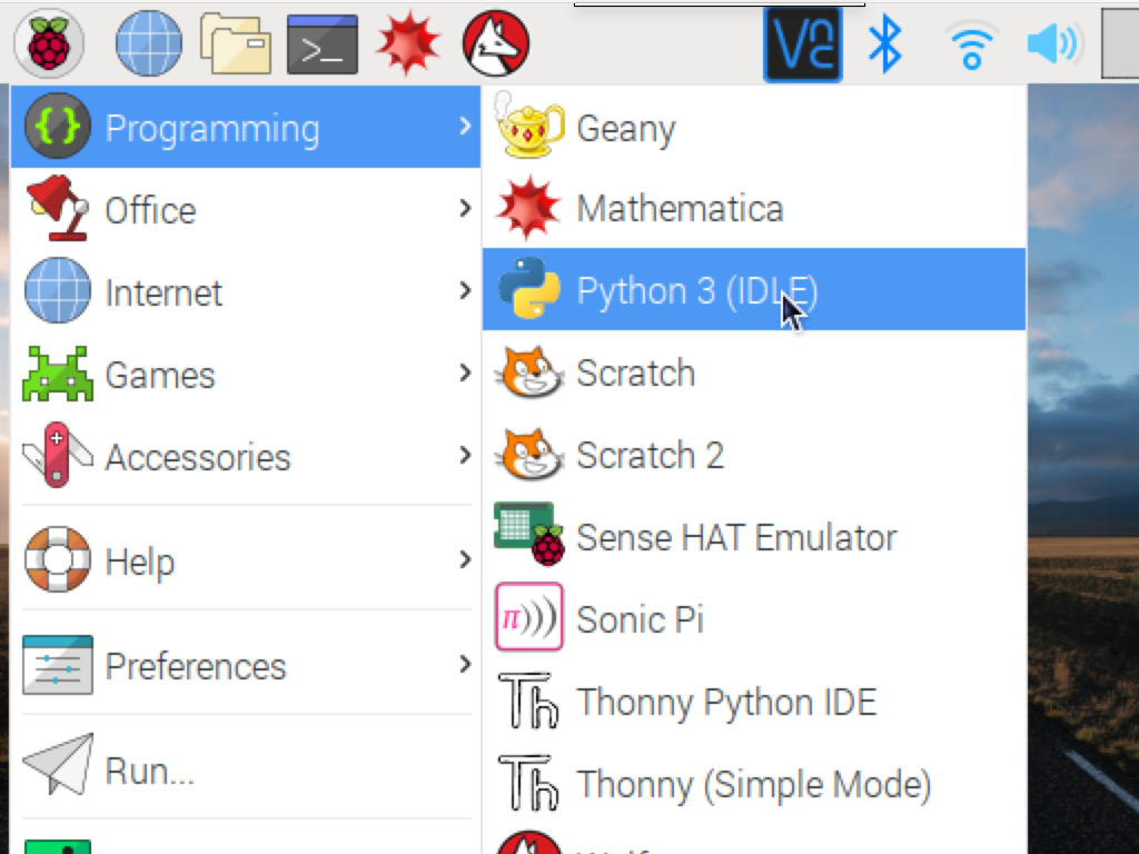

Click on the Raspberry Pi icon on the top left hand corner to access the main menu.
Click on Programming > Python 3 (IDLE).
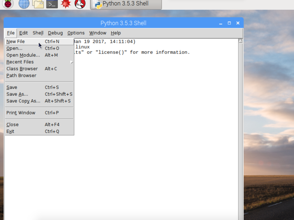
Now, create a new file by clicking File > New File.
Next, save the file by clicking File > Save, and naming it blink.py
from gpiozero import LED
from time import sleep
led = LED(21)
while True:
    led.on()
    sleep(1)
    led.off()
    sleep(1)
Then we import the sleep function from time library. This will enable a pause when turning the LED on and off: from time import sleep
Previously, we connected the LED to GPIO21 and GND of the Raspberry Pi. So, we will assign the led variable to GPIO 21 in the line: led = LED(21).
The LED will be powered up whenever we set it to on in the code: led.on()
To create a never-ending loop which will switch the LED on and off, we use:
while True:
To ensure a pause of 1 second between each change, we use:
sleep(1)
Now, enter the following code into your Python file. First, we import the LED class from GPIO Zero by using: from gpiozero import LED
Feel free to change this value from '1' to another number if you would like there to be a longer pause. Remember to save the python file!