Using an LED with micro:bit
Learn to use an external LED with the micro:bit
Written By: Cherie Tan
Difficulty
Easy
Steps
9
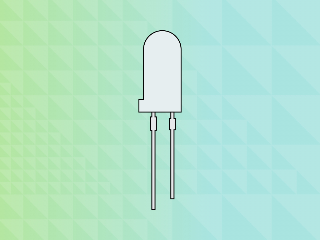
A light-emitting diode (LED) is a semiconductor device that emits light when an electric current passes through it.
In this guide, you will learn to connect a single external LED to the micro:bit and program it in Makecode.
Complete this guide to learn how to use an external LED with the micro:bit!
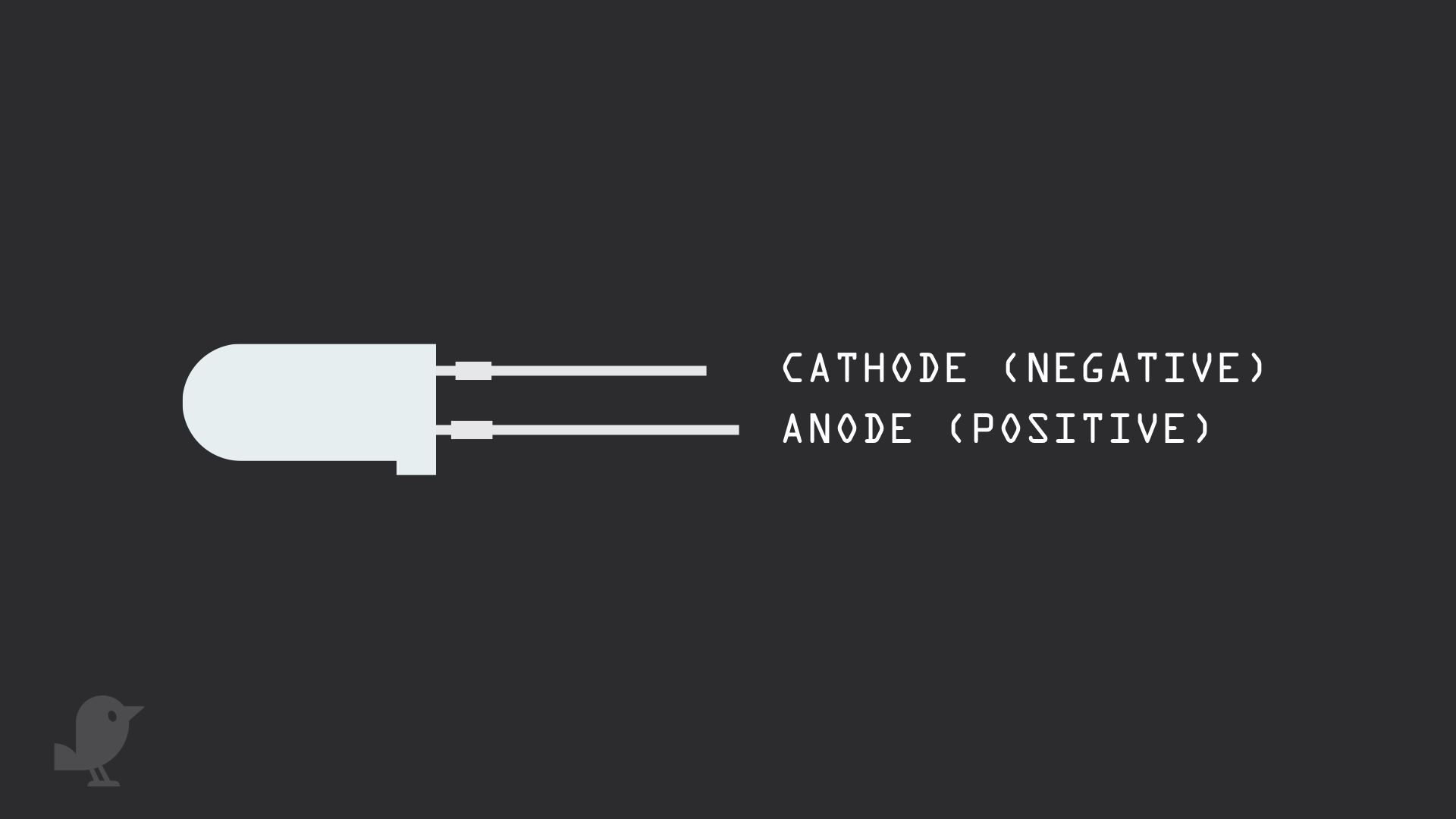
Let's take a look at the external LED. The LED has two leads, a negative lead and a positive lead.
The longer leg is the positive lead, also called the anode.
The shorter leg is the negative lead, also called the cathode. This will be connected to GND.
If the legs are trimmed, you can also tell by looking at the flat edge on the LED's outer casing. The pin closest to the flat edge will be the negative pin, the cathode pin.
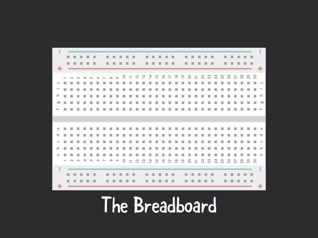
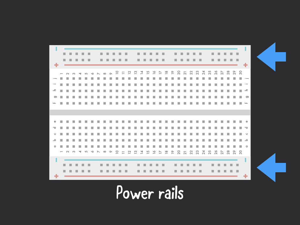
In this guide, we'll be using a 400-tie breadboard. These breadboards have conductive material that connects the holes (known as points) inside the breadboard.
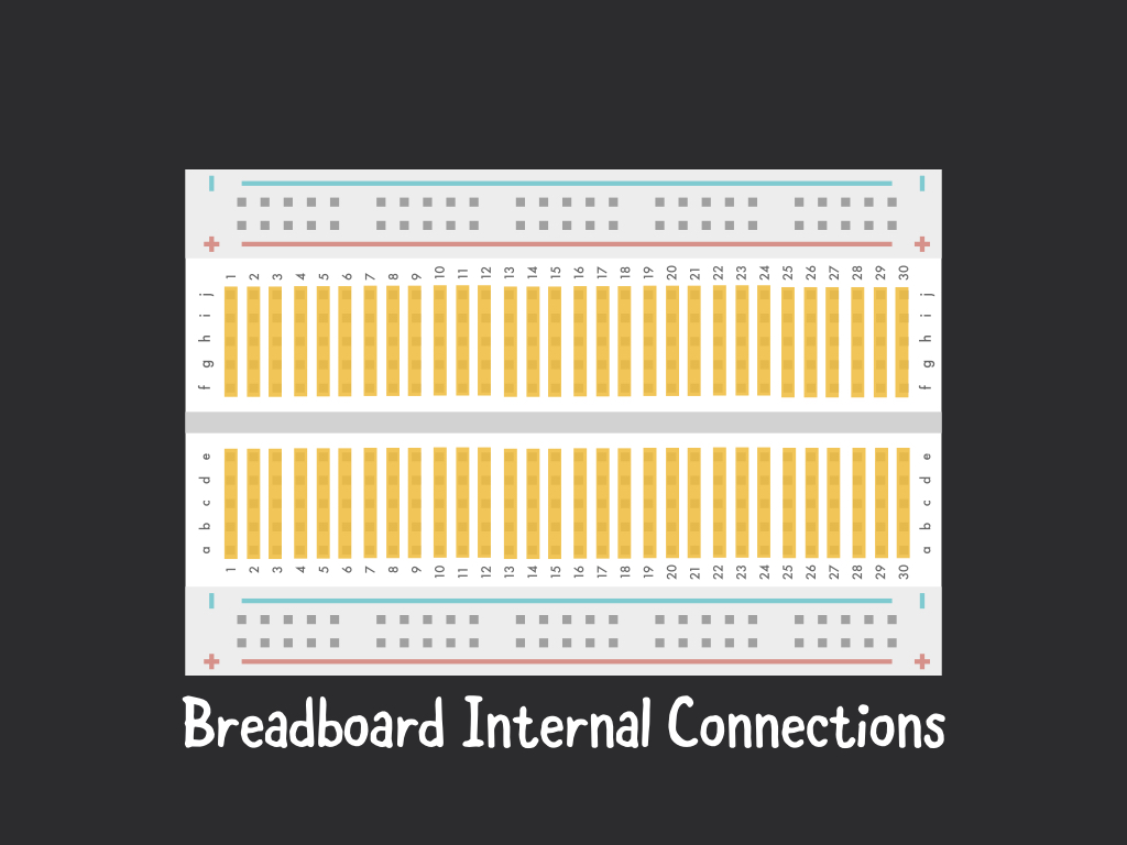
The breadboard points are connected to each other vertically, with a trough in the middle that enables more prototyping area.
The conductive material (and electrically joined points) are shown in this diagram in gold.
The power rails are labelled '+' and '-'. The holes on the power rail are to each other horizontally.
The power rails are used to connect to '3.3V' and 'GND' on the micro:bit.
basic.forever(function () {
    pins.digitalWritePin(DigitalPin.P2, 0)
    basic.pause(500)
    pins.digitalWritePin(DigitalPin.P2, 1)
    basic.pause(500)
})
To turn the LED on and off, we'll use 'pins.digitalWritePin()' and 'basic.pause()'
Copy and paste the following code to the Javascript interface
We've set its first parameter to 'DigitalPin.P2' as the LED is connected to Pin 2 on the micro:bit. Its second parameter can be '0' to turn the LED off or '1' to turn the LED on.
The equivalent code in Makecode blocks can be seen by going to the 'Blocks' interface. To do so, click on the 'Blocks' button.

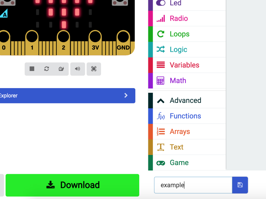
To upload the code to the micro:bit, click the download button in the bottom left corner of the screen.
This will download a hex file (computer program file) which the micro:bit can read.
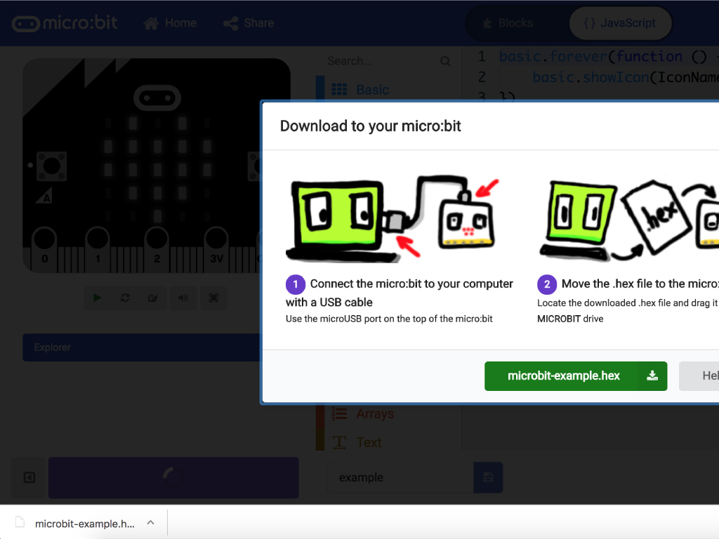
Next, plug in your micro:bit, this will reveal a USB on your computer.
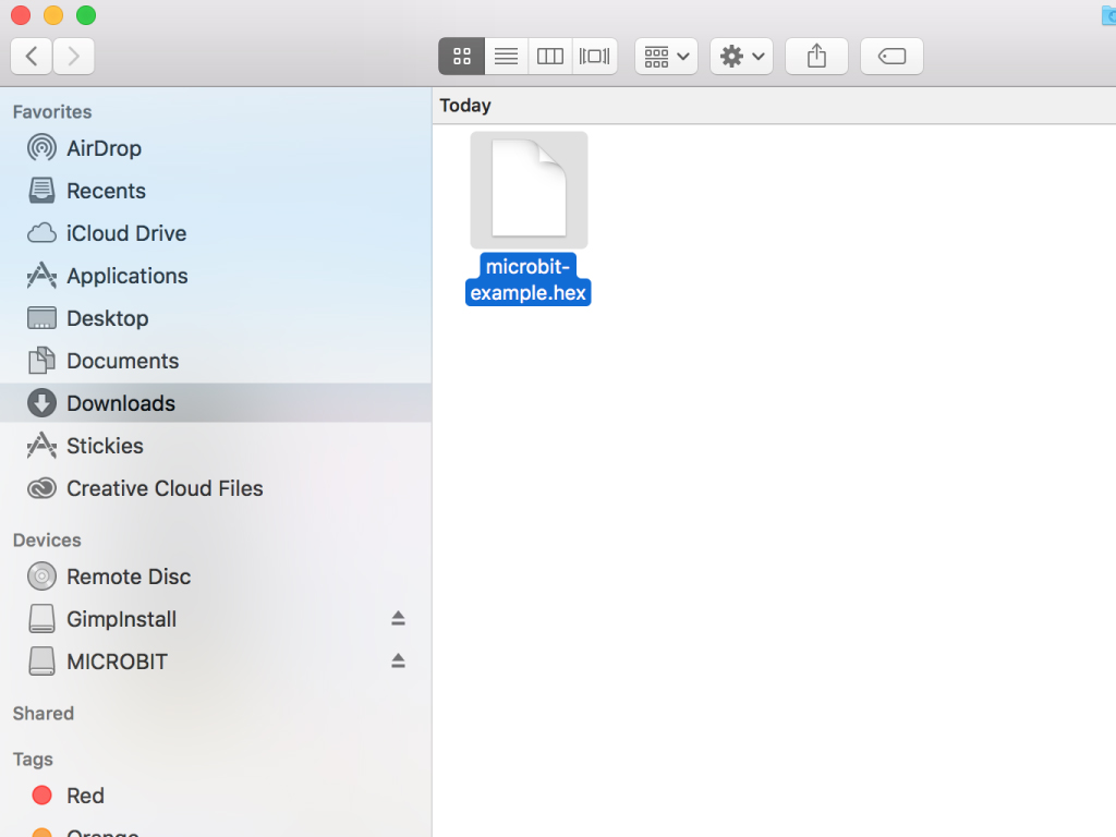
Copy across the downloaded file to the micro:bit by dragging and dropping it to the MICRO:BIT drive
The micro:bit will flash as the code is being uploaded. Once done, unplug the micro:bit.
led.enable(false)
basic.forever(function () {
    pins.digitalWritePin(DigitalPin.P3, 0)
    basic.pause(500)
    pins.digitalWritePin(DigitalPin.P3, 1)
    basic.pause(500)
})
Some pins share function with on-board components like the pushbuttons or LED display. To use them with the LED, the LED display will first need to be disabled.
For instance, by default, Pin 3 is used to control the first column of the micro:bit's LED display.
For instance, by default, Pin 3 is used to control the first column of the micro:bit's LED display.
To use it with the LED, we'll need to use this line of code: led.enable(false)
Alternatively, if you are using the Blocks interface: Click on the 'Led' tab and add a 'led enable false' block to the 'on start' block.
Alternatively, if you are using the Blocks interface: Click on the 'Led' tab and add a 'led enable false' block to the 'on start' block.
For more information on what each pin does, check out our guide, 'Meet the micro:bit'.
To upload the code to the micro:bit, first click the download button in the bottom left corner of the screen. This will download a hex file (computer program file) which the micro:bit can read.
Next, plug in your micro:bit, this will reveal a USB on your computer.
Copy across the downloaded file to the micro:bit by dragging and dropping it to the MICRO:BIT drive
The micro:bit will flash as the code is being uploaded. Once done, unplug the micro:bit.