Hall Effect Sensor with micro:bit
Detect the presence of magnetic fields
Written By: Cherie Tan
Difficulty
Easy
Steps
12
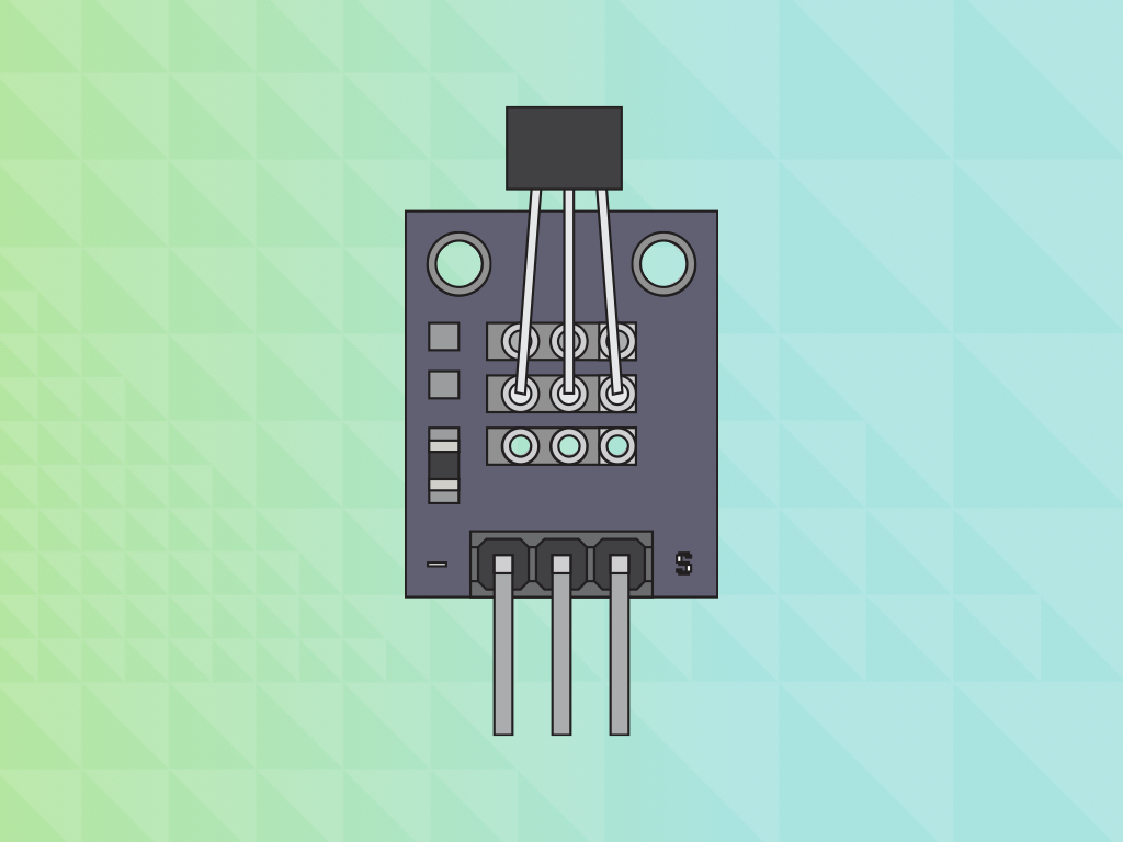
A hall effect sensor consists of a thin rectangular conductor material, that can be used to detect the presence of magnetic fields. Normally, no current flows through the circuit. But in the presence of a magnetic field, the hall effect sensor turns 'ON' and current can flow through the circuit.
In this guide, learn to connect it to the micro:bit using a breakout board and breadboard, and get it to turn on an LED when a magnet is near.
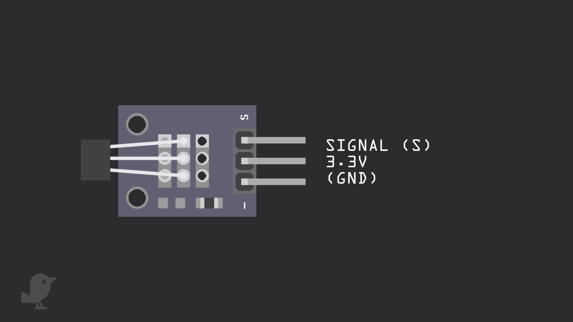
First, let's take a closer look at the hall effect sensor module. There are three pins:
S : This is the signal pin which we will connect to a GPIO pin on the micro:bit
3.3V : Though it is unlabelled on the module, this middle pin will need to be connected to 3.3V on the micro:bit
GND: This pin is labelled '-' on the module, it is a 'GND' pin. What's 'GND'? In electronics, we define a point in a circuit to be a kind of zero volts or 0V reference point, on which to base all other voltage measurements. This point is called ground or GND.
Voltage is the difference in potential between two points. As it is difficult to talk about voltage without a reference point, we need another point to compare it to.
The hall effect sensor, similar to the reed switch, varies its output voltage in response to changes in the magnetic field. While both function the same in that way, the hall effect sensor has no moving parts. The second difference is that it activates when a magnetic field is perpendicular to the sensor.
pins.setPull(DigitalPin.P0, PinPullMode.PullUp)
This line of code 'pins.setPull(DigitalPin.P0, PinPullMode.PullUp)' configures the electrical pull of pin P0 as a pull-up.
Because digital input pins are very sensitive to change. As a result, its value will be a random, constantly changing value. When P0 is not LOW or HIGH, but fluctuating, it is said to be 'floating' at an unknown value. Now, if you were to skip to step 4, removed this line of code and uploaded the code, the LED will not light up.
A pull-up resistor, or the micro:bit's in-built solution counters this problem. You simply use this line of code, or the equivalent 'set pull pin P0 to up' block!
Once you've got MakeCode editor up and running, start a new project.
Copy and paste this code to the Javascript interface.
Copy and paste this code to the Javascript interface.
let sensorVal = 0
basic.forever(function () {
    sensorVal = pins.digitalReadPin(DigitalPin.P0)
})
Copy and paste this code into the Javascript interface.
Now in the 'forever' block, we will first create a variable, 'sensorVal'.
'digitalReadPin()' is used to read the state of pin P0.
The variable, 'sensorVal' stores this information.
'digitalReadPin()' is used to read the state of pin P0.
The variable, 'sensorVal' stores this information.
let sensorVal = 0
pins.setPull(DigitalPin.P0, PinPullMode.PullUp)
basic.forever(function () {
    sensorVal = pins.digitalReadPin(DigitalPin.P0)
    if (sensorVal == 1) {
        pins.digitalWritePin(DigitalPin.P1, 1)
    } else if (sensorVal == 0) {
        pins.digitalWritePin(DigitalPin.P1, 0)
    }
})
Replace the code with the following in the Javascript interface.
We have now added a conditional 'if ... else if' statement.
let sensorVal = 0
pins.setPull(DigitalPin.P0, PinPullMode.PullUp)
basic.forever(function () {
    sensorVal = pins.digitalReadPin(DigitalPin.P0)
    if (sensorVal == 1) {
        pins.digitalWritePin(DigitalPin.P1, 1)
    } else if (sensorVal == 0) {
        pins.digitalWritePin(DigitalPin.P1, 0)
    }
    basic.showNumber(sensorVal)
})
Replace the previous code with this in the Javascript interface.
After uploading this code to the Micro:bit, grab a magnet from your fridge! Place the magnet close to the hall effect sensor. You will notice that the LED will light up as the 5x5 LED matrix shows '0'. Press the reset button on the back of the micro:bit and the LED will stop lighting up. The value will also be '1'.
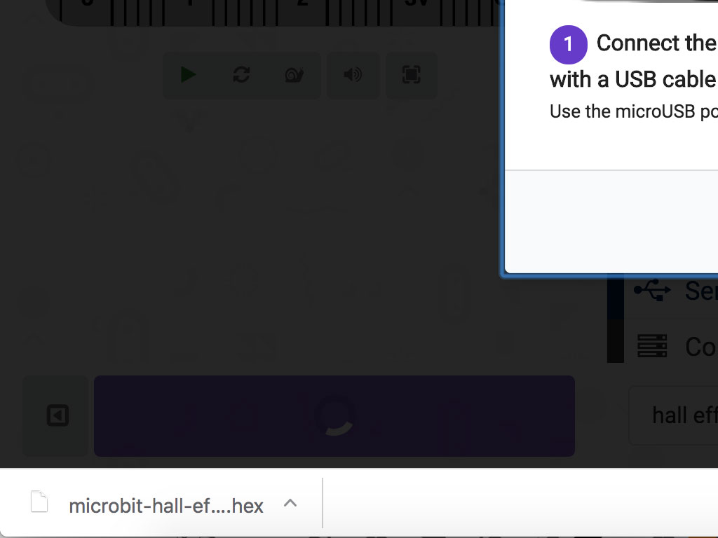
Finally, upload the code to the micro:bit and test it out. Connect the micro:bit to your computer using a microUSB cable
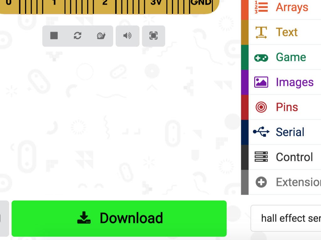
Click on the 'Download' button on the bottom left corner in MakeCode editor
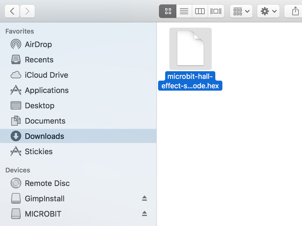
Once downloaded, you can find the hex file in your 'Downloads' folder.
Drag and drop it to the MICROBIT drive