Create a Light-sensitive Alarm with micro:bit
Learn to use the buzzer module and make your own light-sensitive alarm!
Written By: Cherie Tan
Difficulty
Easy
Steps
19
A buzzer is an audio signalling device. There are two types of buzzers, a passive buzzer and an active buzzer. In this guide, we will learn to differentiate between the two, then connect a passive buzzer module to the micro:bit and get it to play a song and change its bpm with a button press.
A light dependent resistor will also be added to the circuit, to create an alarm clock that automatically rings when it gets bright.
After completing this guide, you will understand the basics involved in using a buzzer, and can go on to make your own creations.
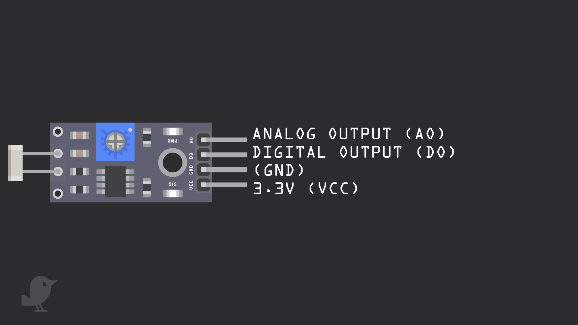
Let's take a closer look at the light-dependent resistor module as well as the buzzer module. The light-dependent resistor module has four pins:
3.3V : While 'VCC' stands for Voltage Common Collector, we'll connect the VCC pin to 3.3V on the micro:bit
GND: In electronics, we define a point in a circuit to be a kind of zero volts or 0V reference point, on which to base all other voltage measurements. This point is called ground or GND.
Note: Voltage is the difference in potential between two points. As it is difficult to talk about voltage without a reference point, we need another point to compare it to.
DO: Digital Output
AO: Analog Output
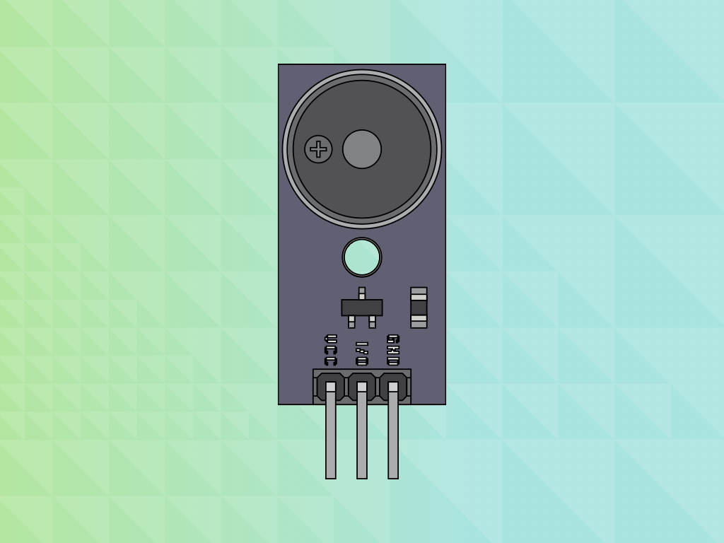
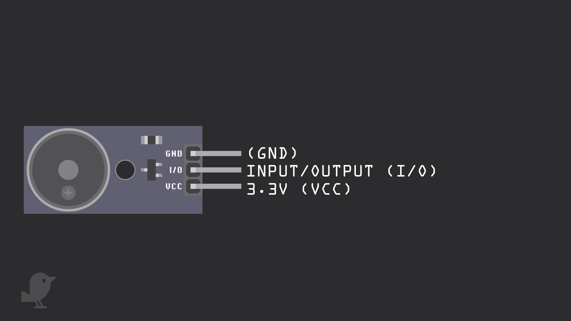
The buzzer module has three pins:
3.3V : While 'VCC' stands for Voltage Common Collector, we'll connect the VCC pin to 3.3V on the micro:bit
I/O: Input/Output
GND
3.3V : While 'VCC' stands for Voltage Common Collector, we'll connect the VCC pin to 3.3V on the micro:bit
I/O: Input/Output
GND
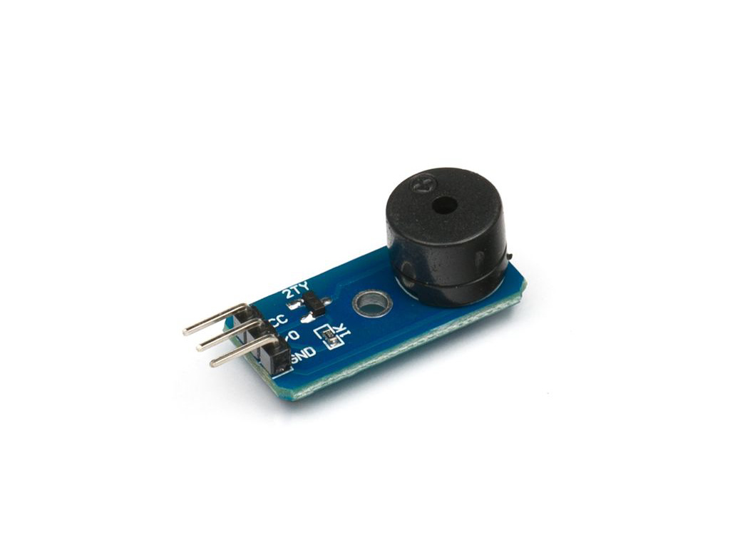
There are two buzzer modules in the kit. Open up the 'Day 15' bag as well, one of the buzzer modules only has a + on the top as shown in the third image, while the other has 'HYDZ' written on it.
One is a passive buzzer while the other is an active buzzer. An active buzzer has additional circuitry in it, and it can generate its own tone. On the other hand, a passive buzzer is like a speaker, where a changing input signal produces the sound. If you put them side by side, the active buzzer is the slightly taller one.
basic.forever(function () {
    pins.digitalWritePin(DigitalPin.P0, 0)
    basic.pause(1000)
    pins.digitalWritePin(DigitalPin.P0, 1)
    basic.pause(1000)
})
Before we begin, let's take a look at the difference between the two buzzer modules.
Use this same MakeCode for both buzzers, swapping them out one after the other. Copy and paste this code to the Javascript interface.
Use this same MakeCode for both buzzers, swapping them out one after the other. Copy and paste this code to the Javascript interface.
Upload this MakeCode to the Micro:bit to hear the difference.
Using the passive buzzer module, you will hear a faint ticking sound as it does not produce its own tone. The active buzzer module will produce a loud beep. In the following MakeCode examples, we will be using the passive buzzer module.
music.beginMelody(music.builtInMelody(Melodies.PowerUp), MelodyOptions.Forever)
First, open up MakeCode editor
Click on 'New Project'
Copy and paste this code into the Javascript interface
input.onButtonPressed(Button.A, function () {
    music.changeTempoBy(5)
})
music.beginMelody(music.builtInMelody(Melodies.Nyan), MelodyOptions.Forever)
We can also change the bpm (beats per minute) of the tune. Replace the existing code with this in the Javascript interface.
let lightVal = 0
basic.forever(function () {
    lightVal = pins.analogReadPin(AnalogPin.P1)
})
You can play all sorts of sounds with a buzzer module and a micro:bit. But what about making a light-sensitive alarm clock with it? So let's add a light dependent resistor to the circuit. The alarm will automatically sound when it gets bright enough.
We will set a threshold level value for this brightness level. Firstly, create a variable for 'lightVal' which is short for light value using: let lightVal = 0
This will store the analog value rather than digital value (1 or 0) of the light level.
let lightVal = 0
basic.forever(function () {
    lightVal = pins.analogReadPin(AnalogPin.P1)
    basic.showNumber(lightVal)
})
Replace the code with the following in the Javascript interface
To set the threshold level, let's take a look at how bright it is around your surroundings using:
basic.showNumber(lightVal)
basic.showNumber(lightVal)
let lightVal = 0
basic.forever(function () {
    lightVal = pins.analogReadPin(AnalogPin.P1)
    basic.showNumber(lightVal)
    if (lightVal < 600) {
        music.beginMelody(music.builtInMelody(Melodies.PowerUp), MelodyOptions.Once)
    }
})
Replace the code with the following in the Javascript interface
The loop will run forever until the micro:bit is turned off.
Try changing the tune to a longer one such as 'birthday' or 'entertainer' then upload this code to your Micro:bit now. You might realise that only part of the tune plays. To play a full tune, use the next MakeCode.
let lightVal = 0
let playingMusic = 0
music.onEvent(MusicEvent.MelodyEnded, function () {
    playingMusic = 0
})
playingMusic = 0
basic.forever(function () {
    lightVal = pins.analogReadPin(AnalogPin.P1)
    if (lightVal < 600 && playingMusic == 0) {
        music.beginMelody(music.builtInMelody(Melodies.Entertainer), MelodyOptions.Once)
        playingMusic = 1
    }
    basic.showNumber(lightVal)
})
let lightVal = 0
basic.forever(function () {
    lightVal = pins.analogReadPin(AnalogPin.P1)
    basic.showNumber(lightVal)
    if (lightVal < 600) {
        pins.digitalWritePin(DigitalPin.P0, 0)
        basic.pause(500)
        pins.digitalWritePin(DigitalPin.P0, 1)
        basic.pause(500)
    }
})
Optionally, if you want to use the active buzzer instead, you can. Copy and paste this code into the Javascript interface, replacing the previous code.
To upload the code to the micro:bit, first connect the micro:bit to the computer via microUSB cable
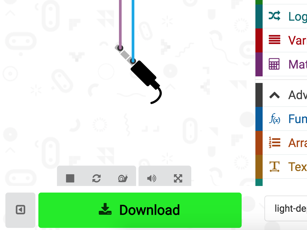
Click on the 'Download' button and the hex file will be automatically downloaded to your 'Downloads' folder
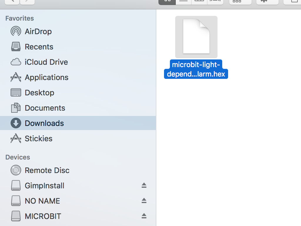
Drag and drop the downloaded .hex file to the MICROBIT drive
Leave the micro:bit alone for a few seconds as it blinks. The code is uploading.
Once powered up, the buzzer will sound the alarm when it gets bright. Cover the light dependent resistor with your hands, and the buzzer will stop making sound!