Pushbutton with micro:bit
Learn how to add an external pushbutton to the micro:bit
Written By: Cherie Tan
Difficulty
Easy
Steps
13
While the micro:bit already has two on-board push buttons, button A and button B, you can add more buttons to control the micro:bit.
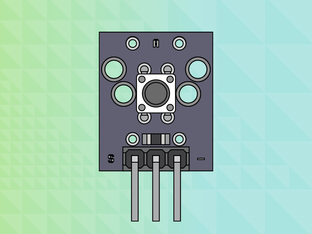
In this guide, you will learn to connect an external push button to the micro:bit, and get it to turn turn an LED on and off. The push button module is comprised of a momentary push button switch and an in-built resistor.
After completing this guide, you will know how to add more buttons to your micro:bit which will come in handy when you go on to make all sorts of projects.
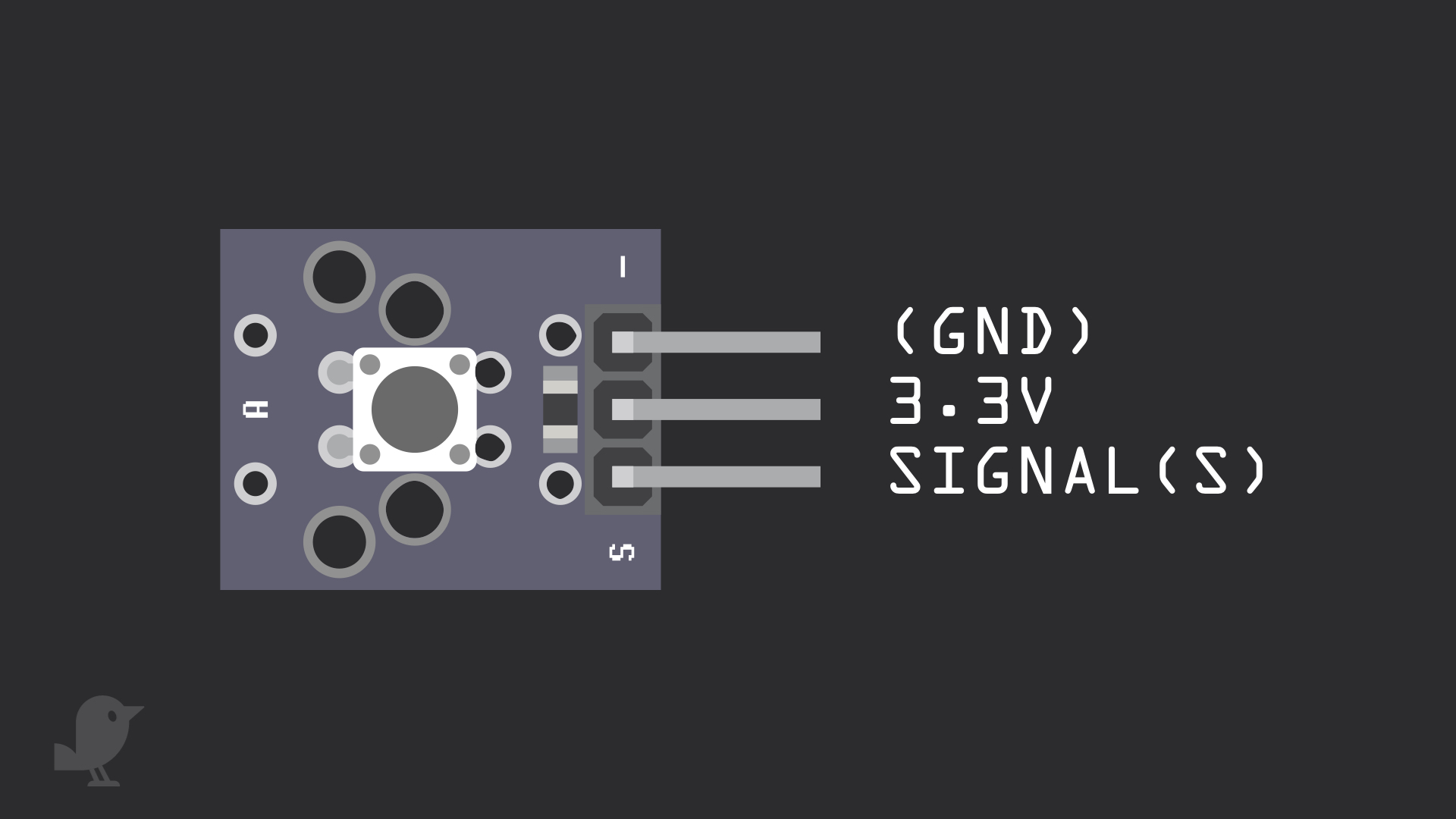
Before we put together the circuit, let's take a closer look at the Pushbutton Module. There are three pins here:
S : This is the signal pin which we will connect to a GPIO pin on the micro:bit
3.3V : Though it is unlabelled on the module, this middle pin will need to be connected to 3.3V on the micro:bit
GND: In electronics, we define a point in a circuit to be a kind of zero volts or 0V reference point, on which to base all other voltage measurements. This point is called ground or GND.
Voltage is the difference in potential between two points. As it is difficult to talk about voltage without a reference point, we need another point to compare it to.
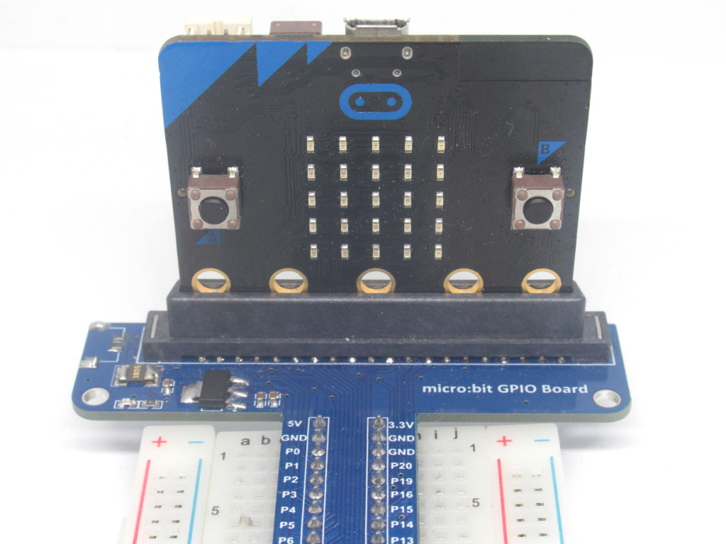
Insert the micro:bit into the breakout board . Make sure that the micro:bit is inserted in the right orientation, with the buttons facing inward as shown.
pins.setPull(DigitalPin.P0, PinPullMode.PullNone)
pins.setEvents(DigitalPin.P0, PinEventType.Edge)
Now open up MakeCode editor
Click on 'New Project'
Copy and paste the following code into the Javascript interface.
input.onPinPressed(TouchPin.P0, function () {
    pins.digitalWritePin(DigitalPin.P1, 1)
})
pins.setPull(DigitalPin.P0, PinPullMode.PullNone)
pins.setEvents(DigitalPin.P0, PinEventType.Edge)
Copy and paste this code into the Javascript interface in the MakeCode editor.
input.onPinPressed(TouchPin.P0, function () {
    pins.digitalWritePin(DigitalPin.P1, 1)
})
input.onPinReleased(TouchPin.P0, function () {
    pins.digitalWritePin(DigitalPin.P1, 0)
})
pins.setPull(DigitalPin.P0, PinPullMode.PullNone)
pins.setEvents(DigitalPin.P0, PinEventType.Edge)
After testing out the previous code, replace it with this in the Javascript interface.
To transfer the code to the micro:bit, follow these steps. Connect the micro:bit to your computer using a microUSB cable
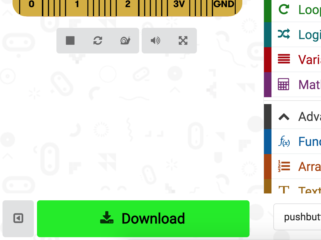
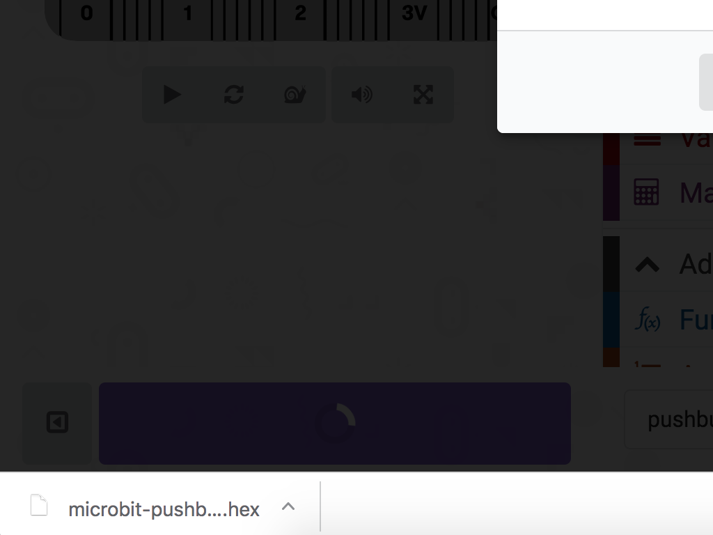
Click on the 'Download' button in MakeCode editor. It should be on the bottom left-hand corner.
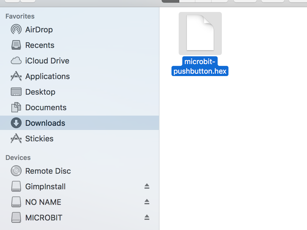
Locate the downloaded .hex file in your 'Downloads' folder.
Drag and drop the .hex file to the MICROBIT drive.
Test the code out! Press the push button and the LED should light up briefly. Let it go and it should stop lighting up.