Meet the micro:bit
Learn about the micro:bit's key features as well as the SPI and I2C protocols
Written By: Cherie Tan
Difficulty
Easy
Steps
8
Welcome to the exciting world of the micro:bit!
In this guide, you'll be introduced to the micro:bit and its key features, and learn about the SPI and I2C communication protocols.
Complete this guide to gain a basic understanding of the micro:bit, and easily use it with a wide variety of add-ons.
Welcome to the fun and exciting world of the micro:bit! What is the micro:bit? It's a pocket-sized microcontroller board designed by the BBC and it's been gaining worldwide popularity. It can be used to form the heart of a complex robotic system, a home security project, or simply to show a heart icon when you press a button. With its versatility and low barrier to entry, it can help a beginner develop their computational thinking skills, programming skills and learn about how electronics work.
To get started you'll typically need some of the following parts below:
- BBC Micro:Bit
- MicroUSB Cable
- Computer with USB port
- Access to the internet
- Alligator Cables or the Edge Connector
- Battery Pack
Many of these parts are in the MicroBit Kits assembled by Little Bird.
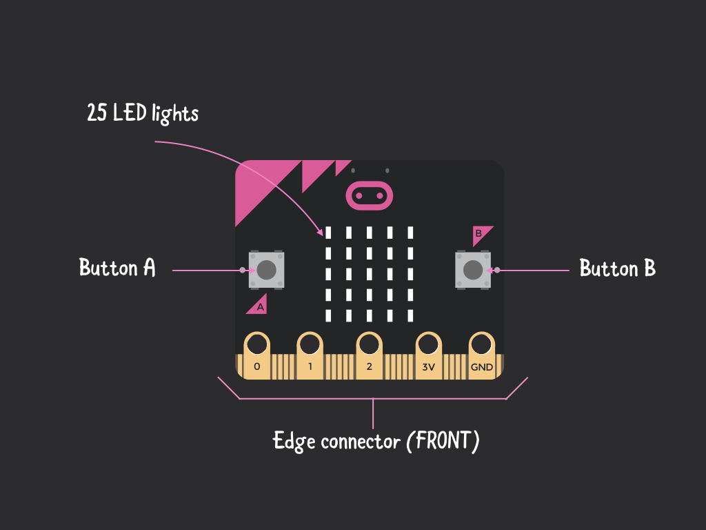
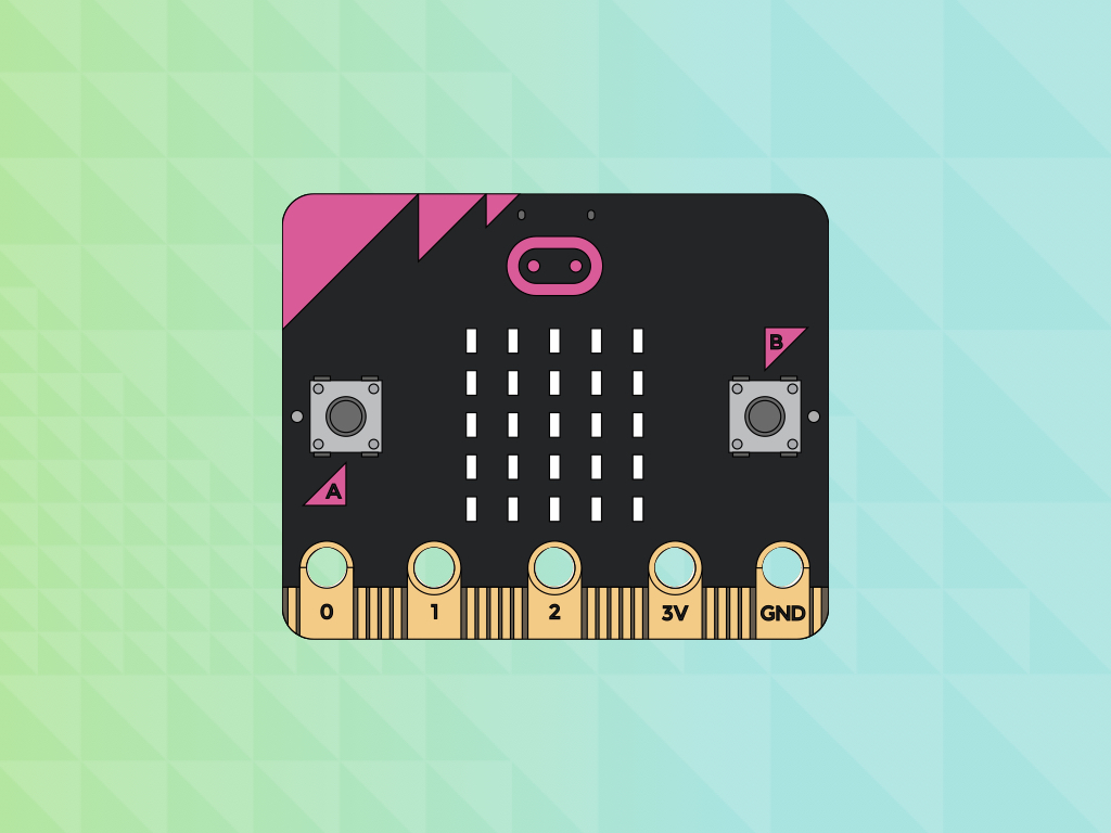
Before you get started with coding it though, we recommend getting familiar with its key features. Get out your micro:bit and examine it. There are two sides to the micro:bit. The front side has two momentary pushbuttons, Button A and Button B.
It also has 25 LED lights or pixels that serves the same purpose as a computer monitor; you can use it to display smiley faces, sensor data, games or important messages of all kinds.
An edge connector with a total of 25 pins that allows you to connect to various sensors and actuators by accessing its inputs and outputs, and connect to power or ground.
There are 5 giant pins that are labelled '0', '1', '2', '3V' and 'GND' .
These giant pins can easily be connected to via alligator clips
These giant pins can also be accessed using the edge connector breakout board, but for quick prototyping, alligator clips are recommended.
The pin marked 3V is used to power your circuit
The large '0', '1', and '2' pins are General Purpose Input/Output (GPIO) pins:
These pins can be used as inputs or outputs
They do not interfere with other onboard switches, LEDs etc. On the other hand, some of the small pins are shared with other components on the micro:bit
Each of these pins is connected to a shared analog to digital converter or ADC for short. This simply means it can read a range of values apart from just '1' or '0'. This also means you can connect it to components like a light sensor that provides analog signals.
The pin marked GND is the ground and completes the circuit.
We'll take a closer look at the small pins later in this guide.
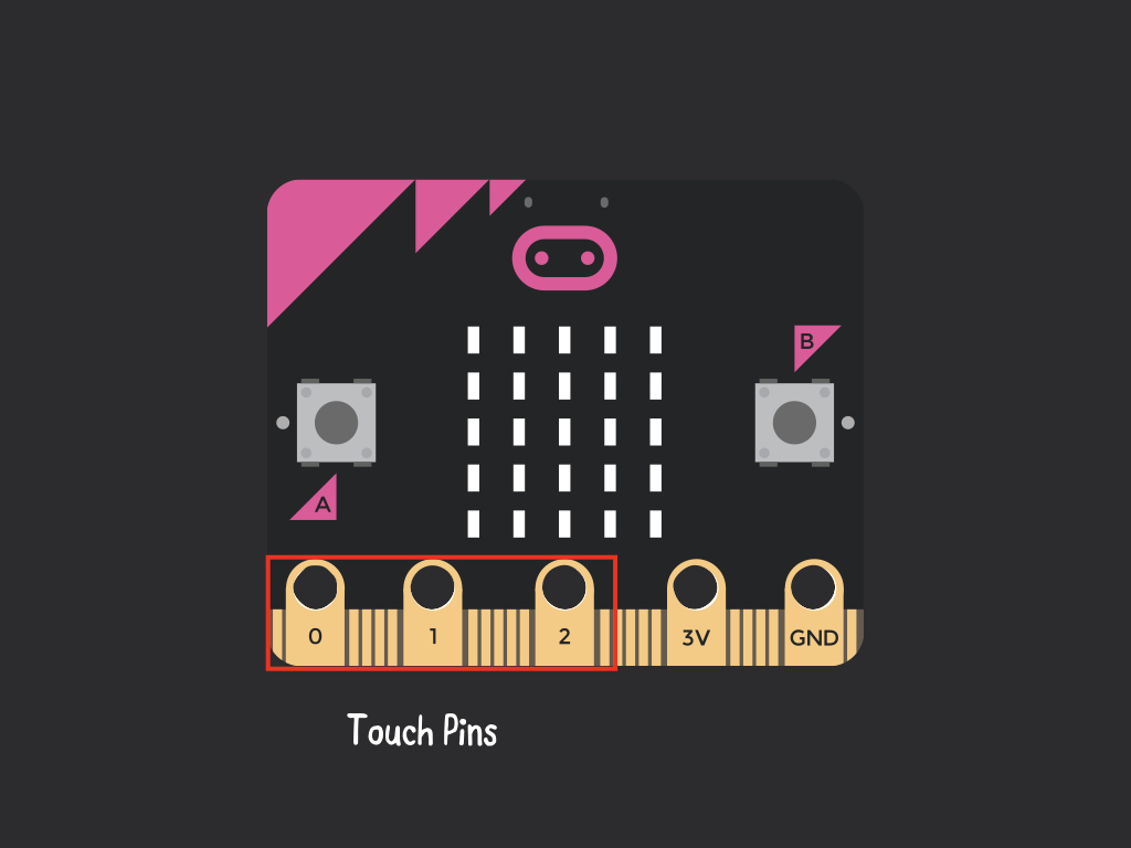
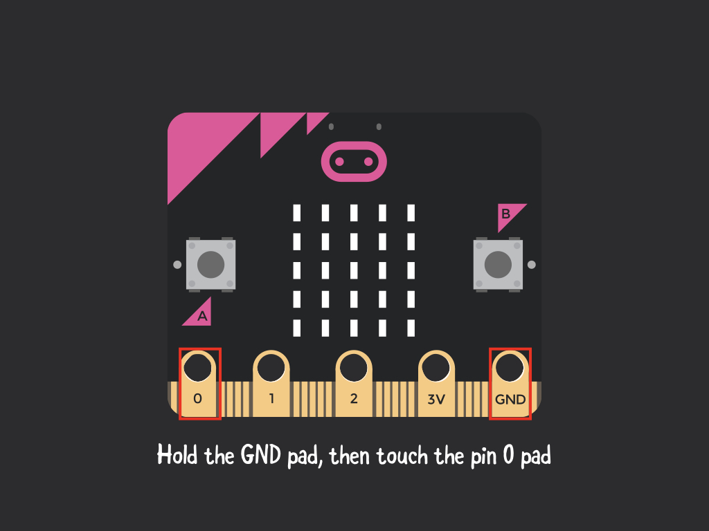
The three specialized pins with large connector pads, '0', '1' and '2' are also known as 'touch pins'. This basically means the micro:bit can detect when you touch one of them with your finger.
By programming the micro:bit in MakeCode or Micropython, and then holding the GND pad with a finger, and touching Pin 0 with another finger, the micro:bit will detect and react accordingly.
These three pins support touch, analog and digital signals.
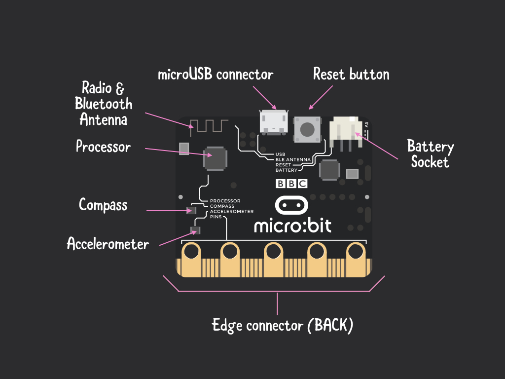
Over on the back side of the micro:bit are a bunch of features:
- A built-in accelerometer
- A built-in compass
- Radio and bluetooth antenna
- MicroUSB connector
- Reset button
- Battery socket
- Processor (Nordic nRF51822): 16MHz 32-bit ARM Cortex-M0 CPU, 256KB flash memory, 16KB Static RAM
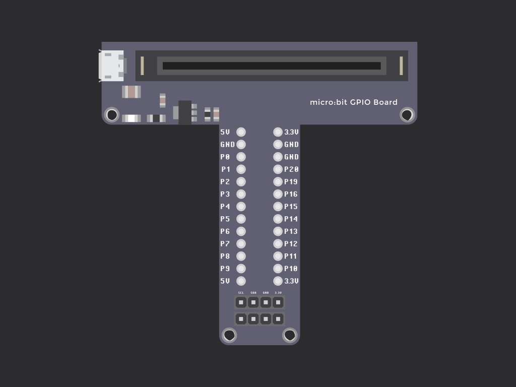
Unlike the five large pins, the other 20 smaller pins on the edge connector aren't designed for use with alligator clips. Instead, there is the option to attach the micro:bit to a breakout board, such as the one found in our Little Bird Micro:Bit 24 Project Kit.
The first thing to note about these smaller pins: They are shared with some on-board hardware.
For example:
- Pin 3 is used to control the first column of the micro:bit's LED display
- Pin 5 is connected to Button A
- Pin 11 is connected to Button B
This doesn't mean you can't use these pins in your own circuits for other uses, but it does mean you can't use them at the same time with the on-board hardware. So if you used pin 3 for something else, it cannot be used to control the first column of the micro:bit's LED display.
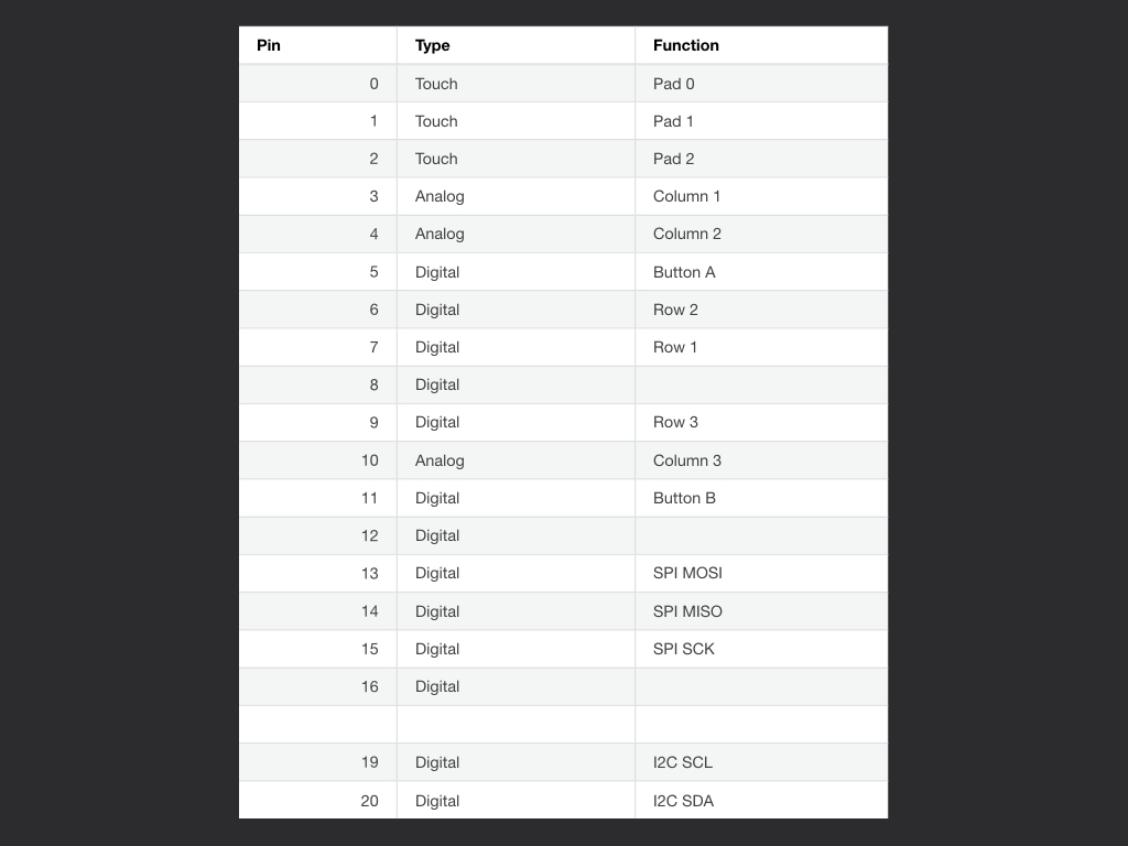
- As you might notice from the table, pins 5, 6, 7, 8, 9, 11, 12, and 16 can be used for digital signals.
- On the other hand, Pin 3, 4 and 10 can be used for analog signals. They are also connected to the same analog to digital converter (ADC).
- Pins 17 and 18 are wired to the 3V supply, like the large ‘3V’ pad.
- Pins 21 and 22 are wired to the GND pin and serve no other function
- What about pins 13, 14, 15, 16, 19 and 20? We'll get to that next!
It allows multiple devices to communicate with each other over typically short distances.
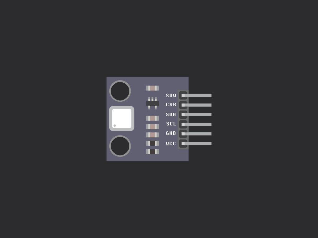
It is used to communicate with more complex add-ons such as a 0.96'' OLED screen with the micro:bit. Yup, by using the SCL (Pin 19) and SDA (Pin 20) pins on the micro:bit, it is possible to connect to other devices and communicate through the I2C bus. This also means that I2C only requires two wires to communicate.
What's more, it is often found used in micro-controllers like the micro:bit, single-board computers like the Raspberry Pi, as well as many sensors ranging from external OLED screens to GPS modules. Therefore, I2C remains one of the easiest ways to communicate with external devices and sensors.
I2C stands for Inter-integrated Circuit and it is a communication protocol.
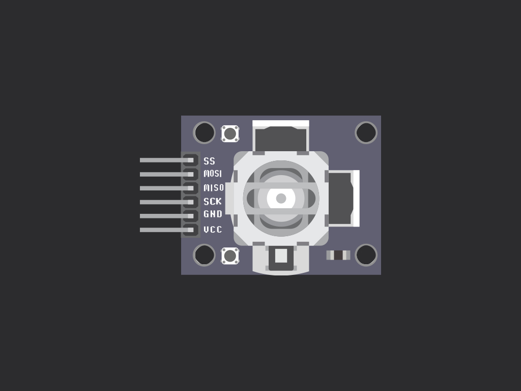
SPI stands for Serial Peripheral Interface (SPI) bus, and allows you to connect devices to the micro:bit through the SPI bus.
- It is commonly used to communicate with add-on devices such as displays and keypads.
- Compared to I2C, it requires three wires to communicate.
- On the micro:bit, SPI can be used by connecting devices on Pins 13 through 15:
- Pin 13 - Serial Clock (SCK) signal
- Pin 14- Master Input Slave Output (MISO) signal
- Pin 15 - Master Output Slave Input (MOSI) signal
- Pin 16 - Dedicated GPIO (conventionally also used for SPI ‘Chip Select’ function).
When connecting devices to the micro:bit via SPI, make sure they are wired in the right order: SCK with SCK, MISO with MISO, MOSI with MOSI.
