Ferroelectric RAM with Arduino
Read and write data to this super-fast, high-endurance, non-volatile memory
Written By: Cherie Tan
Difficulty
Medium
Steps
23
Ferroelectric RAM also known as FRAM, is a type of non-volatile memory that is not only much faster than flash memory and EEPROM, but it has a very high endurance -- each byte can be read and written 10,000,000,000,000 times. Therefore it makes for an excellent alternative to EEPROM for low-power, data-logging applications, where data loss can be prevented in the event of a power loss.
In this guide, learn to use FRAM with the Little Bird Uno R3 and a DHT11 temperature and humidity sensor. The latest temperature reading will be saved to the FRAM, and then retrieved on power start.
Complete this guide to get started with using FRAM for your data-logging applications.
In this guide, learn to use FRAM with the Little Bird Uno R3 and a DHT11 temperature and humidity sensor. The latest temperature reading will be saved to the FRAM, and then retrieved on power start.
Complete this guide to get started with using FRAM for your data-logging applications.
You may be familiar with random access memory, or RAM for short. In the Arduino, RAM is where a sketch creates and manipulates variables while the program is running. It is a type of volatile memory, where data is lost when the power is cut off or if the Arduino is restarted. However, the great thing about RAM is that it has an unlimited write-cycle, so it does not physically deteriorate from use.
On the other end, there is non-volatile memory, where data is retained even if power is cut off. One example of non-volatile memory is flash memory; Every time a sketch is uploaded and stored on the Arduino, this data is retained through the use of flash memory. You may also be familiar with using EEPROM with the Arduino. For both, there is a limitation: they have finite endurance (of around 10,000 cycles for Flash, and 100,000 write cycles for EEPROM), and a slow erase/write process.
On the other end, there is non-volatile memory, where data is retained even if power is cut off. One example of non-volatile memory is flash memory; Every time a sketch is uploaded and stored on the Arduino, this data is retained through the use of flash memory. You may also be familiar with using EEPROM with the Arduino. For both, there is a limitation: they have finite endurance (of around 10,000 cycles for Flash, and 100,000 write cycles for EEPROM), and a slow erase/write process.
Ferroelectric RAM also known as FRAM, or FeRAM, or even F-RAM, is a type of non-volatile memory that is not only much faster than flash memory, but it has a very high endurance. That aside, it is also known for having a higher resistance to gamma-ray irradiation than flash memory or EEPROM, as it does not store information as electric charges, which are significantly influenced by gamma. Therefore, It can be found used in radio frequency identification (RFID) tags, for instance, which are commonly attached to medical equipment that comes in contact with and sterilised by gamma rays. Other uses of FRAM can be found in data logging where the integrity of the data needs to be kept. That is to say, FRAM can be used to avoid the problem of data corruption from power loss or physical deterioration to the chip.
According to the datasheet, the memory cells used in the MB85RS64V (the chip on the SPI FRAM breakout board) can be used for 10^12 read/write operations, which is a significant improvement over the number of read and write operations supported by Flash memory and EEPROM.
In this guide, learn to save data from a DHT11 temperature and humidity sensor to the SPI FRAM breakout board.
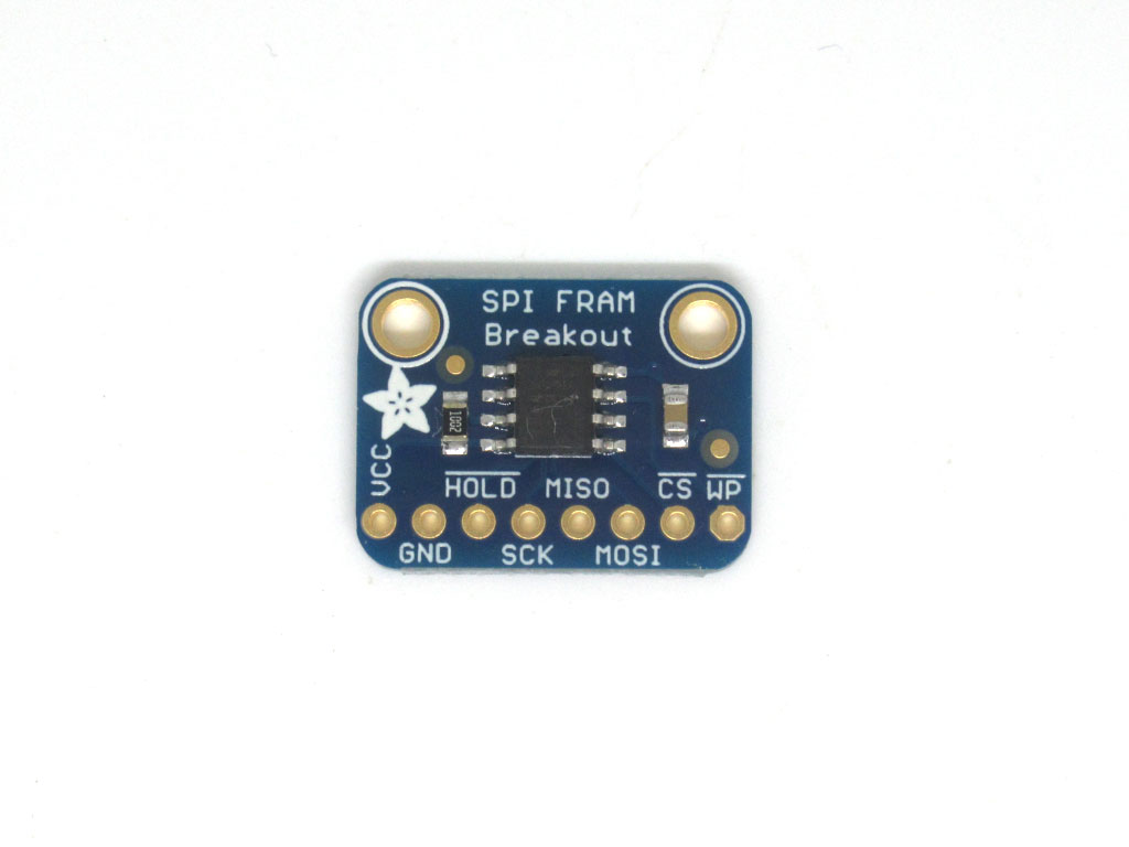
This non-volatile FRAM breakout board from Adafruit is based on the MB85RS64V chip, and has 8KB of storage and can run up to 20MHz speed. Each byte can be read and write to instantaneously, and will keep the memory for 95 years at room temperature.
As mentioned in the overview, the MB85RS64V chip has an endurance of 10^12 read /write cycles - that's 10,000,000,000,000 times! So you don't have to worry too much about wear levelling.
As mentioned in the overview, the MB85RS64V chip has an endurance of 10^12 read /write cycles - that's 10,000,000,000,000 times! So you don't have to worry too much about wear levelling.
Wear leveling is at technique for prolonging the life of some kinds of erasable computer storage media, such as flash memory.
The SPI FRAM breakout board has 8 pins:
VCC: Voltage Common Collector. According to the datasheet, the operating power supply voltage for the chip is within the range 3.0 V to 5.5V. So, pick whatever logic voltage you may wish to use; In this guide, the power pin will be connected to 5V.
GND: Ground pin.
HOLD: This pin interrupts serial input/output without making a chip deselect. This means when the HOLD pin is pulled 'LOW', the SPI bus is put on hold without stopping the current transaction.
SCK: As outlined in the SPI and Arduino guide, this is the serial clock pin, it synchronises data transmission and is generated by the master device. Toggling it up and down drives bits to be sent and received.
MISO: this is the Master In Slave Out pin, for data sent from the FRAM to processor
MOSI: this is the Master Out Slave In pin, for data sent from the processor to the FRAM
CS: Also known as slave select (SS), the chip select (CS) pin is used to tell a particular slave device to go active (when pin is pulled LOW) and receive transmission from a master device, or to go to sleep (when pin is pulled HIGH).
WP: This pin controls writing to a status register. It does not directly affect write protection for the entire chip, only the block-protect register which can be set however you want. For more details, see the datasheet's section on "STATUS REGISTER" and "WRITING PROTECT'.
What is write-protection? It is the ability of a hardware device in this case, to prevent new information from being written or old information from being changed. In other words, information can be read, but nothing can be added or modified.
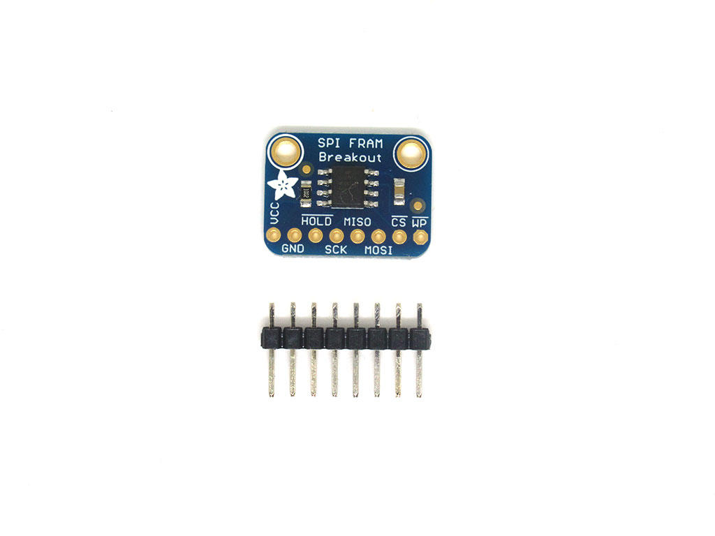
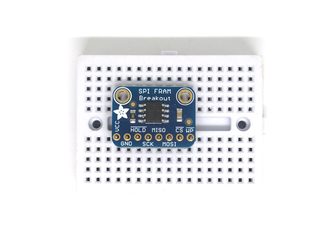
Insert headers into the breakout board.
Align the SPI FRAM breakout board to the headers.
Solder the header pins to the breakout board.
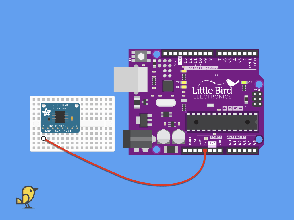
Connect a red jumper wire from VCC on the SPI FRAM breakout board to 5V on the Little Bird Uno R3.
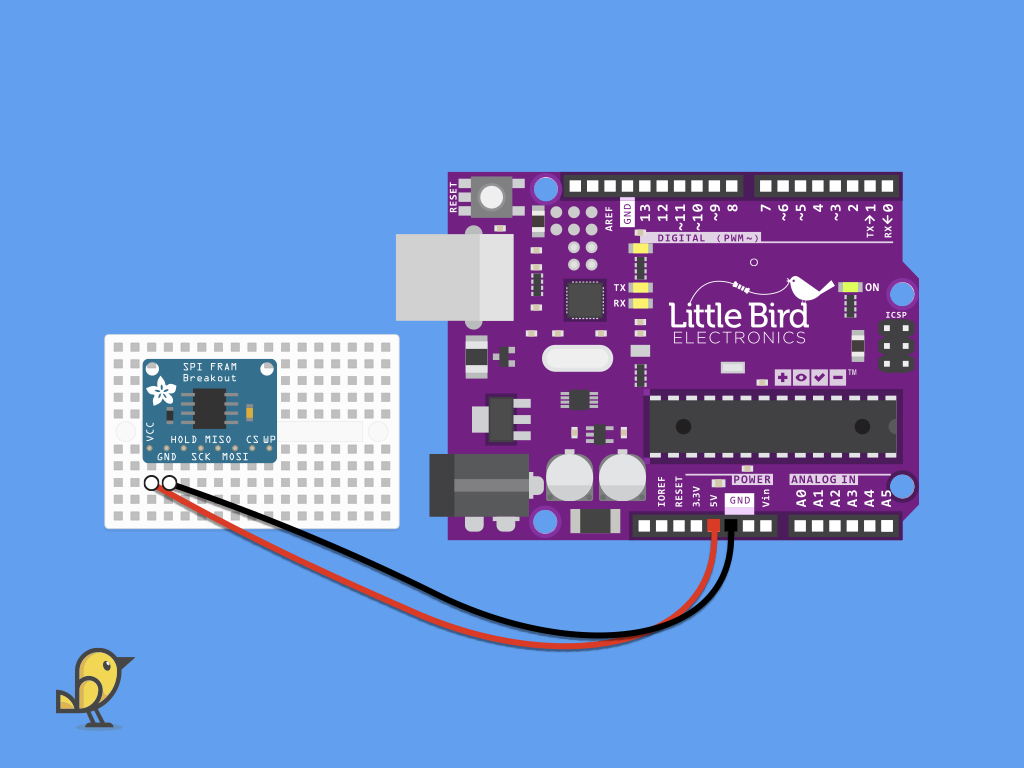
Connect a red jumper wire from GND on the SPI FRAM breakout board to GND on the Little Bird Uno R3.
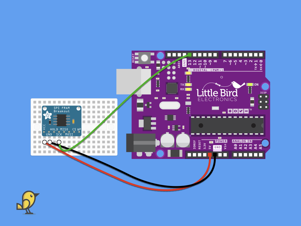
Connect a red jumper wire from SCK on the SPI FRAM breakout board to digital pin 13 on the Little Bird Uno R3.
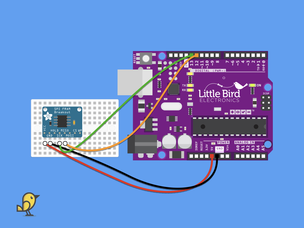
Connect a red jumper wire from MISO on the SPI FRAM breakout board to digital pin 12 on the Little Bird Uno R3.
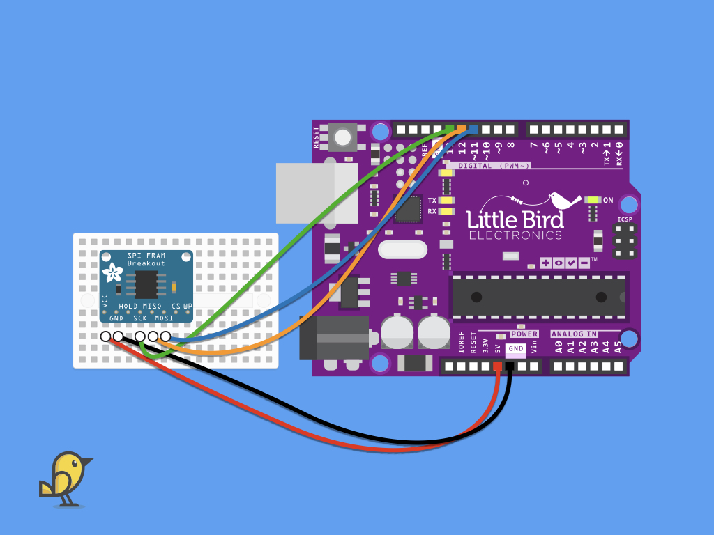
Connect a red jumper wire from MOSI on the SPI FRAM breakout board to digital pin 11 on the Little Bird Uno R3.
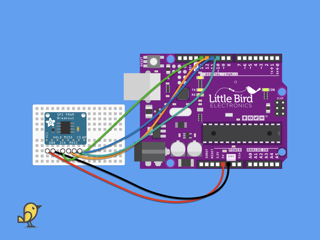
Connect a red jumper wire from CS on the SPI FRAM breakout board to digital pin 10 on the Little Bird Uno R3.
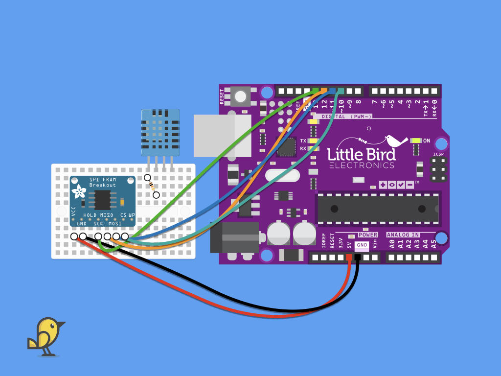
This resistor will pull up the signal line.
Insert a 10k resistor into the mini breadboard, bridging pins 1 and 2 of the DHT11.
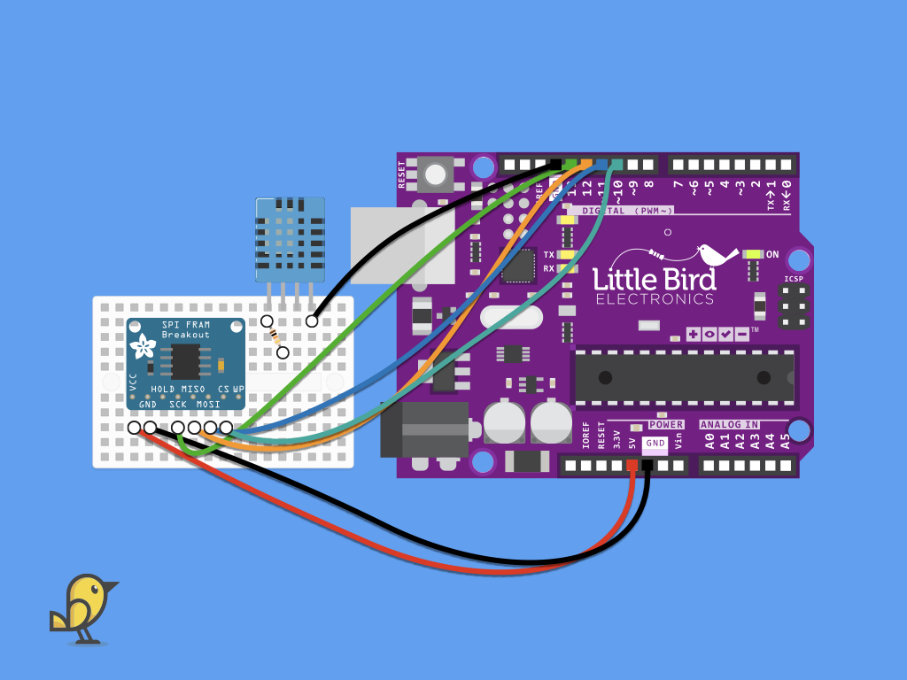
Connect fourth pin of the DHT11, its Ground pin, to GND on the Little Bird Uno R3.
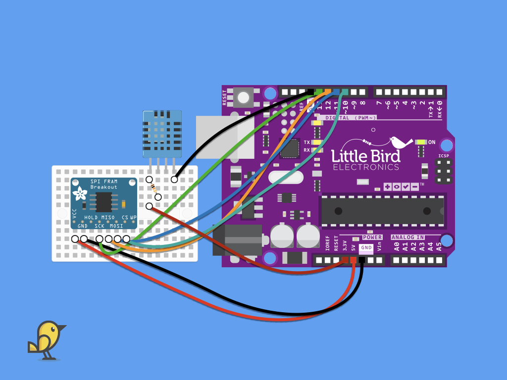
Connect the VCC pin on the DHT11 to 3.3V on the Little Bird Uno R3.
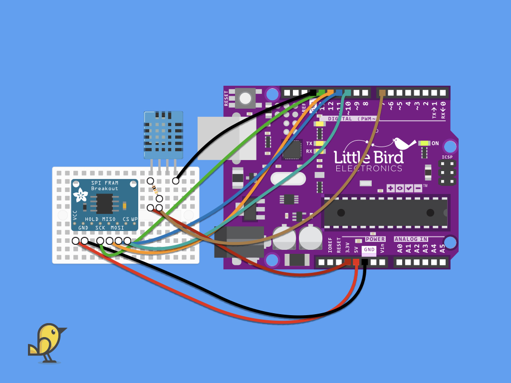
Connect the Data pin on the DHT11 to Digital Pin 7 on the Little Bird Uno R3.
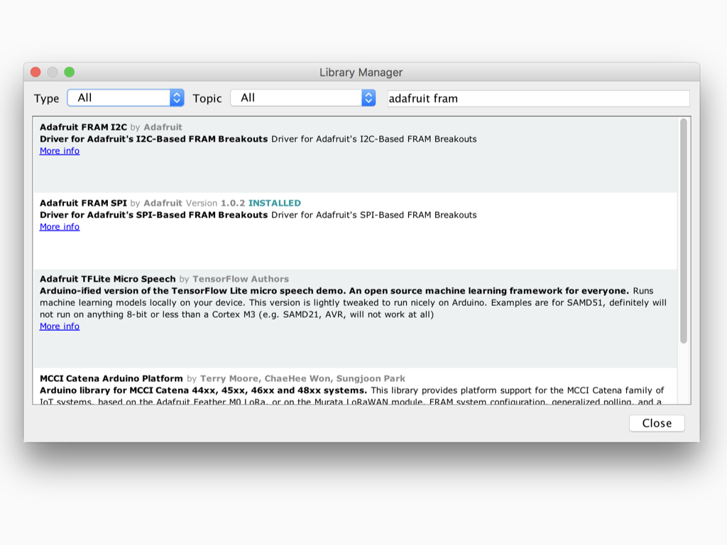
Navigate to Tools > Manage Libraries ...
Type "adafruit fram" into the search field.
Look for 'Adafruit FRAM SPI" and click on the Install button
#include <SPI.h>
#include "Adafruit_FRAM_SPI.h"
#include <SimpleDHT.h>
Then include the Adafruit_FRAM_SPI library.
Next, include the SimpleDHT library.
First, include the SPI library.
#include <SPI.h>
#include "Adafruit_FRAM_SPI.h"
#include <SimpleDHT.h>

const uint8_t FRAM_CS = 10;

Adafruit_FRAM_SPI fram = Adafruit_FRAM_SPI(FRAM_CS);  // use hardware SPI

const uint8_t FRAM_SCK = 13;
const uint8_t FRAM_MISO = 12;
const uint8_t FRAM_MOSI = 11;
const int pinDHT11 = 7;
uint16_t addr = 0;
Next, declare a constant, FRAM_CS requiring 8 bits of memory, representing an unsigned number and initialized with the value 10.
Declare another constant, FRAM_SCK and initialize it with the value 13.
Declare a constant FRAM_MOSI, initialized with the value 11.
Next, create a constant integer variable pinDHT11 and initialize it with the value 7.
Finally, create a variable addr and initialize it with the value, '0'.
Do the same for FRAM_MISO which will be initialized with the value 12, since we have connected the MISO pin of the SPI FRAM breakout to digital pin 12 on the Arduino.
uint8_t represents an unsigned integer type with a width of exactly 8 bits. In other words, it is an unsigned integer number stored in memory, on one byte (or 8 bits) in the Arduino's memory.
Similarly, uint16_t is an unsigned integer type with a width of exactly 16 bits.
Similarly, uint16_t is an unsigned integer type with a width of exactly 16 bits.
#include <SPI.h>
#include "Adafruit_FRAM_SPI.h"
#include <SimpleDHT.h>

const uint8_t FRAM_CS = 10;

Adafruit_FRAM_SPI fram = Adafruit_FRAM_SPI(FRAM_CS);  // use hardware SPI

const uint8_t FRAM_SCK = 13;
const uint8_t FRAM_MISO = 12;
const uint8_t FRAM_MOSI = 11;
const int pinDHT11 = 7;
uint16_t addr = 0;

SimpleDHT11 dht11(pinDHT11);

void setup(void) {

  Serial.begin(9600);

  if (fram.begin()) {
    Serial.println("Found SPI FRAM!");
  } else {
    Serial.println("No SPI FRAM found ... check your connections\r\n");
    while (1);
  }
}
Next, initialize serial communication with the Serial.begin command set to a baud rate of 9600.
Create a conditional statement, where fram.begin will return true or false depending on whether a valid FRAM chip was found. If an FRAM chip was found, print "Found SPI FRAM!" to the serial monitor. Otherwise, "No SPI FRAM found ... check your connections" will be printed.
#include <SPI.h>
#include "Adafruit_FRAM_SPI.h"
#include <SimpleDHT.h>

const uint8_t FRAM_CS = 10;

Adafruit_FRAM_SPI fram = Adafruit_FRAM_SPI(FRAM_CS);  // use hardware SPI

const uint8_t FRAM_SCK = 13;
const uint8_t FRAM_MISO = 12;
const uint8_t FRAM_MOSI = 11;
const int pinDHT11 = 7;
uint16_t addr = 0;

SimpleDHT11 dht11(pinDHT11);

void setup(void) {

  Serial.begin(9600);

  if (fram.begin()) {
    Serial.println("Found SPI FRAM!");
  } else {
    Serial.println("No SPI FRAM found ... check your connections\r\n");
    while (1);
  }
}

void loop() {
  // start working...
  Serial.println("=================================");
  Serial.println("Sample DHT11...");

  // read without samples.
  byte temperature = 0;
  byte humidity = 0;
  int err = SimpleDHTErrSuccess;
  if ((err = dht11.read(pinDHT11, &temperature, &humidity, NULL)) != SimpleDHTErrSuccess) {
    Serial.print("Read DHT11 failed, err="); Serial.println(err);delay(1000);
    return;
  }

  Serial.print("Sample OK: ");
  Serial.print((int)temperature); Serial.print(" *C, ");
  Serial.print((int)humidity); Serial.println(" H");

  // DHT11 sampling rate is 1HZ.
  delay(1500);
}
Copy and paste the following code into the main loop. This will print out temperature and humidity readings from the DHT11 every 1500 milliseconds.
#include <SPI.h>
#include "Adafruit_FRAM_SPI.h"
#include <SimpleDHT.h>

const uint8_t FRAM_CS = 10;

Adafruit_FRAM_SPI fram = Adafruit_FRAM_SPI(FRAM_CS);  // use hardware SPI

const uint8_t FRAM_SCK = 13;
const uint8_t FRAM_MISO = 12;
const uint8_t FRAM_MOSI = 11;
const int pinDHT11 = 7;
uint16_t addr = 0;

SimpleDHT11 dht11(pinDHT11);

void setup(void) {

  Serial.begin(9600);

  if (fram.begin()) {
    Serial.println("Found SPI FRAM!");
  } else {
    Serial.println("No SPI FRAM found ... check your connections\r\n");
    while (1);
  }
}


void loop()
{
  const unsigned long fiveMinutes = 5 * 60 * 1000UL;
  static unsigned long lastSampleTime = 0 - fiveMinutes;  // initialize such that a reading is due the first time through loop()

  unsigned long now = millis();
  if (now - lastSampleTime >= fiveMinutes)
  {
    lastSampleTime += fiveMinutes;
    // add code to take temperature reading here
    // read without samples.
    byte temperature = 0;
    byte humidity = 0;
    int err = SimpleDHTErrSuccess;
    if ((err = dht11.read(pinDHT11, &temperature, &humidity, NULL)) != SimpleDHTErrSuccess) {
      Serial.print("Read DHT11 failed, err="); Serial.println(err); delay(1000);
      return;
    }
    Serial.print((int)temperature); Serial.println(" *C ");
  }
  // add code to do other stuff here
}
Let's imagine that we want to read and then store the latest temperature reading to the FRAM, every five minutes. First, to read the temperature every minute and print it to the serial monitor, copy and paste the following code into the main loop.
#include <SPI.h>
#include "Adafruit_FRAM_SPI.h"
#include <SimpleDHT.h>

const uint8_t FRAM_CS = 10;

Adafruit_FRAM_SPI fram = Adafruit_FRAM_SPI(FRAM_CS);  // use hardware SPI

const uint8_t FRAM_SCK = 13;
const uint8_t FRAM_MISO = 12;
const uint8_t FRAM_MOSI = 11;
const int pinDHT11 = 7;
uint16_t addr = 0;

SimpleDHT11 dht11(pinDHT11);

void setup(void) {

  Serial.begin(9600);

  if (fram.begin()) {
    Serial.println("Found SPI FRAM!");
  } else {
    Serial.println("No SPI FRAM found ... check your connections\r\n");
    while (1);
  }
}


void loop()
{
  const unsigned long fiveMinutes = 5 * 60 * 1000UL;
  static unsigned long lastSampleTime = 0 - fiveMinutes;  // initialize such that a reading is due the first time through loop()

  unsigned long now = millis();
  if (now - lastSampleTime >= fiveMinutes)
  {
    lastSampleTime += fiveMinutes;
    // add code to take temperature reading here
    // read without samples.
    byte temperature = 0;
    byte humidity = 0;
    int err = SimpleDHTErrSuccess;
    if ((err = dht11.read(pinDHT11, &temperature, &humidity, NULL)) != SimpleDHTErrSuccess) {
      Serial.print("Read DHT11 failed, err="); Serial.println(err); delay(1000);
      return;
    }
    Serial.print((int)temperature); Serial.println(" *C ");
    fram.writeEnable(true);
    fram.write8(0x0, temperature)
    fram.writeEnable(false);
  }
  // add code to do other stuff here
}
Next, to save the latest temperature reading to FRAM, writing to the FRAM chip must first be enabled with a call fram.writeEnable(true);
Then use fram.write8(address, byte-value); to write an 8-bit value to the address location. In this sketch, the latest temperature reading is stored in address 0x0.
#include <SPI.h>
#include "Adafruit_FRAM_SPI.h"
#include <SimpleDHT.h>

const uint8_t FRAM_CS = 10;

Adafruit_FRAM_SPI fram = Adafruit_FRAM_SPI(FRAM_CS);  // use hardware SPI

const uint8_t FRAM_SCK = 13;
const uint8_t FRAM_MISO = 12;
const uint8_t FRAM_MOSI = 11;
const int pinDHT11 = 7;
uint16_t addr = 0;

SimpleDHT11 dht11(pinDHT11);

void setup(void) {

  Serial.begin(9600);

  if (fram.begin()) {
    Serial.println("Found SPI FRAM!");
  } else {
    Serial.println("No SPI FRAM found ... check your connections\r\n");
    while (1);
  }
  uint8_t value = fram.read8(0x0);
  Serial.print("Last Temperature:");
  Serial.print(value);
  Serial.println(" *C ");
}


void loop()
{
  const unsigned long fiveMinutes = 5 * 60 * 1000UL;
  static unsigned long lastSampleTime = 0 - fiveMinutes;  // initialize such that a reading is due the first time through loop()

  unsigned long now = millis();
  if (now - lastSampleTime >= fiveMinutes)
  {
    lastSampleTime += fiveMinutes;
    // add code to take temperature reading here
    // read without samples.
    byte temperature = 0;
    byte humidity = 0;
    int err = SimpleDHTErrSuccess;
    if ((err = dht11.read(pinDHT11, &temperature, &humidity, NULL)) != SimpleDHTErrSuccess) {
      Serial.print("Read DHT11 failed, err="); Serial.println(err); delay(1000);
      return;
    }
    fram.writeEnable(true);
    fram.write8(0x0, temperature);
    fram.writeEnable(false);
  }
  // add code to do other stuff here
}
Upload this code to the Little Bird Uno R3, and now on power start up or reboot, the last saved temperature reading will be printed to the serial monitor.
