SPI and Arduino
SPI Library, SPI Modes, Transaction & Transfer methods.
Written By: Cherie Tan
Difficulty
Medium
Steps
16
Serial Peripheral Interface (SPI) is a synchronous serial communication protocol used by many devices to communicate with one another. Fast and capable of full duplex communication (meaning that both devices can send and receive data at the same time), it is commonly used in cases requiring large amounts of data to be transferred, continuously at high speeds. Devices that use the SPI protocol include displays, flash memory, sensors, real-time clocks, etc.
In this guide, learn about the SPI protocol and SPI library.
Complete this guide to gain a better understanding of the SPI library, SPI modes, SPI transaction and transfer methods.
In this guide, learn about the SPI protocol and SPI library.
Complete this guide to gain a better understanding of the SPI library, SPI modes, SPI transaction and transfer methods.
In order for devices to communicate, whether they are computers or microcontrollers, there needs to be a method for communication. In our previous guide on I²C and Arduino, we talked about serial communication, specifically on synchronous and asynchronous serial communication.
Serial Peripheral Interface (SPI) is a synchronous serial communication protocol developed by Motorola back in the mid 1980s. It is widely used between microcontrollers and peripheral ICs such as sensors, displays, flash memory, real-time clocks, shift registers, ADCs, DACs, etc.
In this guide, learn about the SPI protocol, and how to use the SPI library.
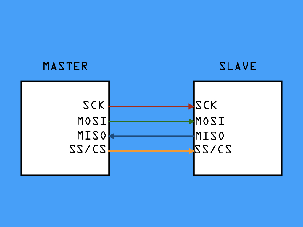
The first difference between I2C and SPI communication: SPI requires the use of four wires.
SCK: Serial Clock (synchronises data transmission and is generated by the master, which toggles it up and down, driving bits being sent and received)
MOSI: Master Output Slave Input (used to send data from master to slave device)
MISO: Master Input Slave Output (used to send data from slave to master device)
SS: Slave Select (Tells the particular slave device to go 'active' and receive transmission from the master device, or to go to sleep. These lines run from the processor to each slave device, it is also known as chip select, CS)
Secondly, SPI supports higher speed full-duplex communication than I2C.
While SPI has an unspecified communication speed, it can be implemented at speeds of 10 Mbps or more.
Why is SPI so much faster than I2C? The unique benefit of SPI is that data can be transferred without interruption. Any number of bits can be sent or received in a continuous stream. In comparison, I2C requires data to be sent in packets -- with a limited number of bits each time, as well as a start and stop condition that defines the end of each packet. This doesn't happen in SPI communication, hence it is faster.
What does full-duplex communication mean? This means when the clock signal is generated by the master device (and only the master device can do so), both master and slave devices are free to communicate at the same time.
So during each SPI clock cycle, a full-duplex data transmission occurs. The master transmits a bit on the MOSI line, which the slave listens for. At the same time, the slave device transmits a bit along the MISO line, and the master listens for it.
Only the master device dictates the data rate, bit order, and SPI mode.
Data rate is the speed of transmission, and is determined by the frequency of the microcontroller's clock signal.
Bit order describes if the rightmost (LSB) or leftmost (MSB) is the first bit out.
We'll go into detail on SPI modes later.
Data rate is the speed of transmission, and is determined by the frequency of the microcontroller's clock signal.
Bit order describes if the rightmost (LSB) or leftmost (MSB) is the first bit out.
We'll go into detail on SPI modes later.
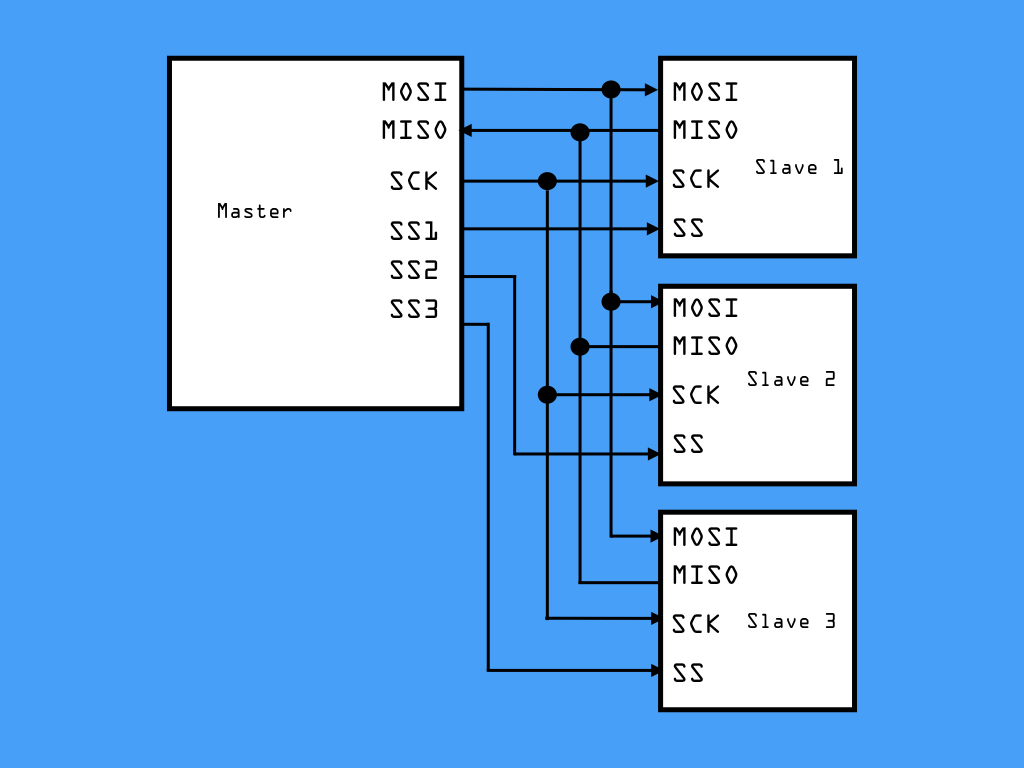
Thirdly, SPI only allows one master device and supports communication with multiple slave devices through the use of an additional chip-select line from the processor to each slave device. Once communication is complete, either with the sending of data or retrieving of data, the master device stops the clock signal and deselects the slave device along this CS line.
Note that three signals are outputs from the master (MOSI, SCK, SS) and one is an input to (MISO).
While it is possible to verify that data is being received correctly in I²C communication, this is not the case with SPI communication.
SPI only supports one master device whereas I²C supports multiple master devices.
SPI can only travel short distances and rarely off the PCB while I²C can transmit data over much greater distances, although at low data rates.
Overall, SPI is the better choice for high-speed, low-power applications where a small number of peripherals need to transfer a large amount of data. On the other hand, I²CC is better suited for communication with a large number of peripherals, where multiple master devices on the same bus may be required, and if you are transferring a small amount of data.
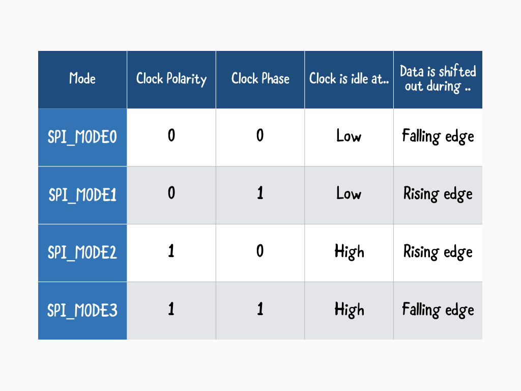
In the SPI protocol, data is sent with respect to the clock pulse. There are four SPI modes.
Clock polarity (CPOL), and clock phase (CPHA) are the main parameters that define a clock format to be used by the SPI bus.
The CPOL parameter determines whether the clock is idle when HIGH or LOW, which determines if the SPI clock is inverted or non-inverted.
The CPHA parameter is used to shift the sampling phase; If CPHA = 0 then the data are sampled on the leading (first) clock edge. Otherwise, if CPHA = 1, the data are sampled on the trailing (second) clock edge.
These modes control whether data is shifted in and out on the rising or falling edge of the data clock signal (called the clock phase), The four modes combine clock polarity and clock phase according to this table:
These modes control whether data is shifted in and out on the rising or falling edge of the data clock signal (called the clock phase), The four modes combine clock polarity and clock phase according to this table:
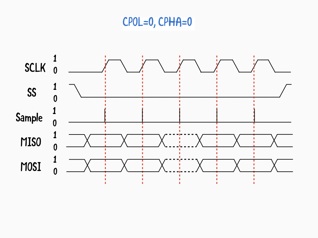
The clock idle state is zero.
The data on MISO and MOSI lines must be stable while the clock is high, and can be changed when the clock is low.
Data is captured on the clock's low-to-high transition, and propagated on high-to-low clock transition.
Let's take a look a closer look at SPI_MODE0, CPOL= 0 and CPHA= 0.
In this mode, data must be available before the first clock signal rising.
In this mode, data must be available before the first clock signal rising.
The clock idle state is zero.
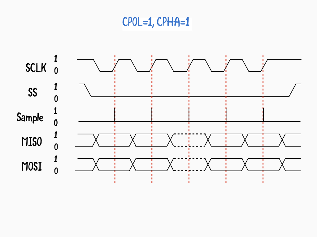
The data on MISO and MOSI lines must be stable while the clock is low and can be changed when the clock is high.
The data is captured on the clock's high-to-low transition and propagated on low-to-high clock transition.
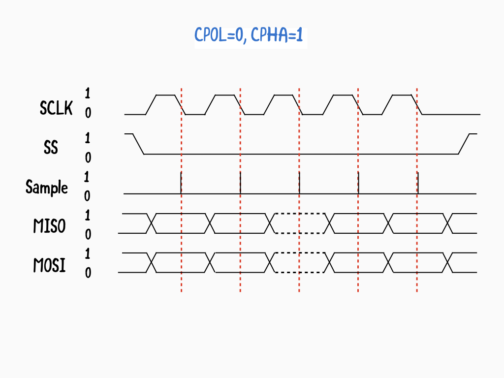
Next, in SPI_MODE1: CPOL=0 and CPHA=1
The first clock signal rising can be used to prepare the data.
The first clock signal rising can be used to prepare the data.
The clock idle state is one.
The data on MISO and MOSI lines must be stable while the clock is low and can be changed when the clock is high.
The data is captured on the clock's high-to-low transition and propagated on low-to-high clock transition.
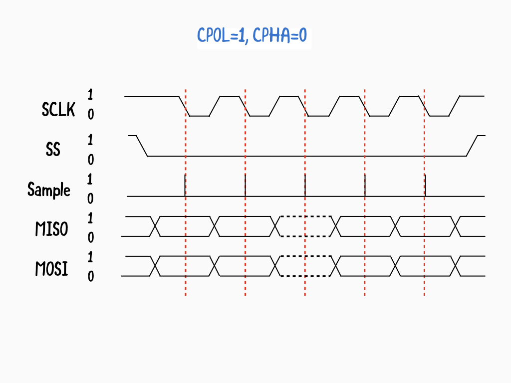
Next, SPI_MODE2: CPOL= 1 and CPHA=0
The data must be available before the first clock signal falling.
The data must be available before the first clock signal falling.
The clock idle state is one.
The data on MISO and MOSI lines must be stable while the clock is high and can be changed when the clock is low.
The data is captured on the clock's low-to-high transition and propagated on high-to-low clock transition.
In SPI_MODE3: CPOL=1 and CPHA=1
The first clock signal falling can be used to prepare the data.
The first clock signal falling can be used to prepare the data.
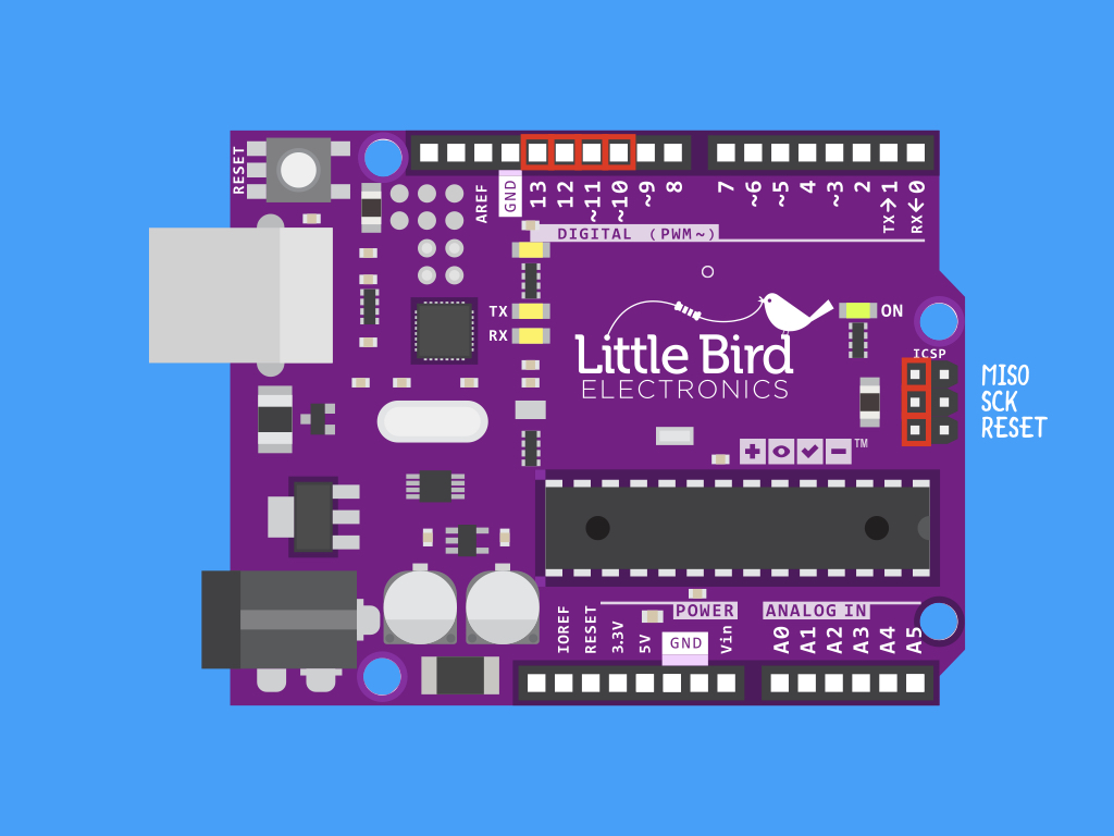
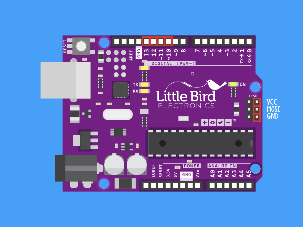
You may notice that the ICSP header does not include any SS pins. Only the MISO, MOSI, SCLK, power and ground connectors are labelled as shown. Note that the Slave Select pins are not used to transfer data, but only to tell a slave that it will be addressed. As such, digital pin 10 is just an arbitrary description; any digital output pin can be used as a Slave Select pin.
MOSI: Digital Pin 11 or ICSP-4
MISO: Digital Pin 12 or ICSP-1
SCK: Digital Pin 13 or ICSP-3
SS: Digital Pin 10
MISO: Digital Pin 12 or ICSP-1
SCK: Digital Pin 13 or ICSP-3
SS: Digital Pin 10
#include <SPI.h>
To begin using the SPI.h library, the first step is to include it in the sketch: #include <SPI.h>
Implementing SPI with a device will be different for each device, and it is recommended to refer to the data sheet.
#include <SPI.h>

void setup() {
  // start the SPI library:
  SPI.begin();
}
Then, start SPI by using the SPI.begin command in the setup function.
#include <SPI.h>

// using two incompatible SPI devices, A and B. Incompatible means that they need different SPI_MODE
const int slaveAPin = 20;
const int slaveBPin = 21;

// set up the speed, data order and data mode
SPISettings settingsA(1000000, MSBFIRST, SPI_MODE1);
SPISettings settingsB(10000000, LSBFIRST, SPI_MODE3);

void setup() {
  // set the Slave Select Pins as outputs:
  pinMode (slaveAPin, OUTPUT);
  pinMode (slaveBPin, OUTPUT);
  // initialize SPI:
  SPI.begin();
}
Sometimes, different SPI setups are required for different devices. For instance, one device may use SPI_MODE0, while another device may use SPI_MODE2. Another instance is when one device operates at a different and much slower speed than the other i.e. 1 MHz vs 10 MHz. In this case, it would make more sense to have a different setup for each.
To do so, configure each SPI device once as an SPISettings object.
To do so, configure each SPI device once as an SPISettings object.
We also need to set up digital outputs for each of the slave select (SS) pins to the slave devices. In this sketch, we've set the SS pins for the two slave devices to be digital pin 20 and digital pin 21.
Next, each slave select pin needs to be set as a digital OUTPUT in setup.
#include <SPI.h>

// using two incompatible SPI devices, A and B. Incompatible means that they need different SPI_MODE
const int slaveAPin = 20;
const int slaveBPin = 21;

// set up the speed, data order and data mode
SPISettings settingsA(1000000, MSBFIRST, SPI_MODE1);
SPISettings settingsB(10000000, LSBFIRST, SPI_MODE3);

void setup() {
  // set the Slave Select Pins as outputs:
  pinMode (slaveAPin, OUTPUT);
  pinMode (slaveBPin, OUTPUT);
  // initialize SPI:
  SPI.begin();
}

uint8_t stat, val1, val2, result;

void loop() {
  // read three bytes from device A
  SPI.beginTransaction(settingsA);
  digitalWrite (slaveAPin, LOW);
  // reading only, so data sent does not matter
  stat = SPI.transfer(0);
  val1 = SPI.transfer(0);
  val2 = SPI.transfer(0);
  digitalWrite (slaveAPin, HIGH);
}
When communicating with a specific SPI device, transaction methods are used. It serves two purposes: (1) To tell the SPI when to start and end when using it within a particular context, and (2) to configure the SPI for a specific chip.
In this sketch, SPI.beginTransaction automatically uses the settings for device A which were declared earlier, settingsA.
In this sketch, SPI.beginTransaction automatically uses the settings for device A which were declared earlier, settingsA.
SPI.beginTransaction disables any interrupts that use SPI for that duration of the transaction.
#include <SPI.h>

// using two incompatible SPI devices, A and B. Incompatible means that they need different SPI_MODE
const int slaveAPin = 20;
const int slaveBPin = 21;

// set up the speed, data order and data mode
SPISettings settingsA(1000000, MSBFIRST, SPI_MODE1);
SPISettings settingsB(10000000, LSBFIRST, SPI_MODE3);

void setup() {
  // set the Slave Select Pins as outputs:
  pinMode (slaveAPin, OUTPUT);
  pinMode (slaveBPin, OUTPUT);
  // initialize SPI:
  SPI.begin();
}

uint8_t stat, val1, val2, result;

void loop() {
  // read three bytes from device A
  SPI.beginTransaction(settingsA);
  digitalWrite (slaveAPin, LOW);
  // reading only, so data sent does not matter
  stat = SPI.transfer(0);
  val1 = SPI.transfer(0);
  val2 = SPI.transfer(0);
  digitalWrite (slaveAPin, HIGH);
  SPI.endTransaction();
  // if stat is 1 or 2, send val1 or val2 else zero
  if (stat == 1) {
   result = val1;
  } else if (stat == 2) {
   result = val2;
  } else {
   result = 0;
  }
}
In this sketch, the SS pin of slave device A is set to LOW, so it is ready to transmit data to the master. But remember, only the master device can generate the clock signal, so the slave device will not be able to transmit this data just yet, without the help of the master device.
In order for the slave device to send data to the master device, the master device must be sending data to the slave device, so that the clock (SCK) is running.
This is where dummy data (typically 0) is used. So, when the slave is ready to transmit a byte of data, the master transmits a byte of placeholder or dummy data to the slave (MOSI). As dummy data is sent to the slave, the slave transmits the real data for the master device (MISO).
When communication is complete, slaveAPin is set to HIGH.
Here, the SPI transfer method is based on a simultaneous send and receive, where it transfers one byte over the SPI bus. As it only sends and receives only a single byte per call, to receive more data, this function will need to be called as many times as needed.
#include <SPI.h>

// using two incompatible SPI devices, A and B. Incompatible means that they need different SPI_MODE
const int slaveAPin = 20;
const int slaveBPin = 21;

// set up the speed, data order and data mode
SPISettings settingsA(1000000, MSBFIRST, SPI_MODE1);
SPISettings settingsB(10000000, LSBFIRST, SPI_MODE3);

void setup() {
  // set the Slave Select Pins as outputs:
  pinMode (slaveAPin, OUTPUT);
  pinMode (slaveBPin, OUTPUT);
  // initialize SPI:
  SPI.begin();
}

uint8_t stat, val1, val2, result;

void loop() {
  // read three bytes from device A
  SPI.beginTransaction(settingsA);
  digitalWrite (slaveAPin, LOW);
  // reading only, so data sent does not matter
  stat = SPI.transfer(0);
  val1 = SPI.transfer(0);
  val2 = SPI.transfer(0);
  digitalWrite (slaveAPin, HIGH);
  SPI.endTransaction();
  // if stat is 1 or 2, send val1 or val2 else zero
  if (stat == 1) {
   result = val1;
  } else if (stat == 2) {
   result = val2;
  } else {
   result = 0;
  }
  // send result to device B
  SPI.beginTransaction(settingsB);
  digitalWrite (slaveBPin, LOW);
  SPI.transfer(result);
  digitalWrite (slaveBPin, HIGH);
  SPI.endTransaction();
}
To end the transaction, use SPI.endTransaction.
SPI.endTransaction re-enables any SPI-using interrupts.
#include <SPI.h>

// using two incompatible SPI devices, A and B. Incompatible means that they need different SPI_MODE
const int slaveAPin = 20;
const int slaveBPin = 21;

// set up the speed, data order and data mode
SPISettings settingsA(1000000, MSBFIRST, SPI_MODE1);
SPISettings settingsB(10000000, LSBFIRST, SPI_MODE3);

void setup() {
  // set the Slave Select Pins as outputs:
  pinMode (slaveAPin, OUTPUT);
  pinMode (slaveBPin, OUTPUT);
  // initialize SPI:
  SPI.begin();
}

uint8_t stat, val1, val2, result;

void loop() {
  // read three bytes from device A
  SPI.beginTransaction(settingsA);
  digitalWrite (slaveAPin, LOW);
  // reading only, so data sent does not matter
  stat = SPI.transfer(0);
  val1 = SPI.transfer(0);
  val2 = SPI.transfer(0);
  digitalWrite (slaveAPin, HIGH);
  SPI.endTransaction();
  // if stat is 1 or 2, send val1 or val2 else zero
  if (stat == 1) {
   result = val1;
  } else if (stat == 2) {
   result = val2;
  } else {
   result = 0;
  }
  // send result to device B
  SPI.beginTransaction(settingsB);
  digitalWrite (slaveBPin, LOW);
  SPI.transfer(result);
  digitalWrite (slaveBPin, HIGH);
  SPI.endTransaction();
}
This time, settingsB is used in SPI.beginTransaction.
Again, the slave select pin for that specific slave device is set to LOW.
The resulting data is then sent to slave device B with SPI.transfer, this time with the previously received value, result as its parameter.
receivedVal = SPI.transfer(val)
receivedVal = SPI.transfer(val)
There are two more parameters you could add when calling the SPI.transfer function. For example, if you specify a Slave Select (SS) pin in the call to SPI.transfer, the specified pin is activated (and subsequently, pulled low) before the transfer occurs and deactivated (pulled high) when the transfer is finished.
If you do not specify a transferMode, by default, it will be SPI_LAST. Here, the SS pin returns to high after one byte of data has been transferred. Use SPI_LAST for the last byte of data to be transferred.
Otherwise, it can also be set to SPI_CONTINUE, here the SS pin stays low until SPI.transfer is called without transferMode, or called with SPI_LAST.
Syntax:
SPI.transfer(val)
SPI.transfer(slaveSelectPin, val)
SPI.transfer(slaveSelectPin, val, transferMode)
val: the value to transfer
slaveSelectPin: slave device SS pin
transferMode: SPI_LAST, or SPI_CONTINUE
Finally, the slave select pin for slave device B is pulled high, and the transaction ends with SPI.endTransaction.