Real-time clock with Arduino
Timekeeping with the DS1307 RTC Module and Arduino
Written By: Cherie Tan
Difficulty
Medium
Steps
12
While the Arduino has a built-in timekeeper called millis(), it only tracks time since the Arduino was last powered. What if you needed timekeeping for even when the Arduino is powered off? The Arduino is not able to tell whether it is a 'Thursday' or a 'Friday', either. For those purposes, a real-time clock module can be used instead.
In this guide, learn to connect a DS1307 Real Time Clock (RTC) Module with the Little Bird - Uno R3 and program it for time-keeping. Then, learn to use the RTC module and interrupts to put the Uno R3 in and out of power-saving mode.
Complete this guide to get started with using the DS1307 RTC Module with Arduino.
While the Arduino has a built-in timekeeper called millis(), it only tracks time since the Arduino was last powered. What if you wanted to keep track of the time in your projects, even when the Arduino is powered off? Also, the Arduino is not able to tell whether it is a 'Thursday' or a 'Friday', either! For those purposes, a real-time clock module can be used instead.
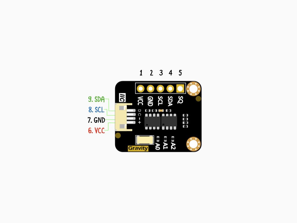
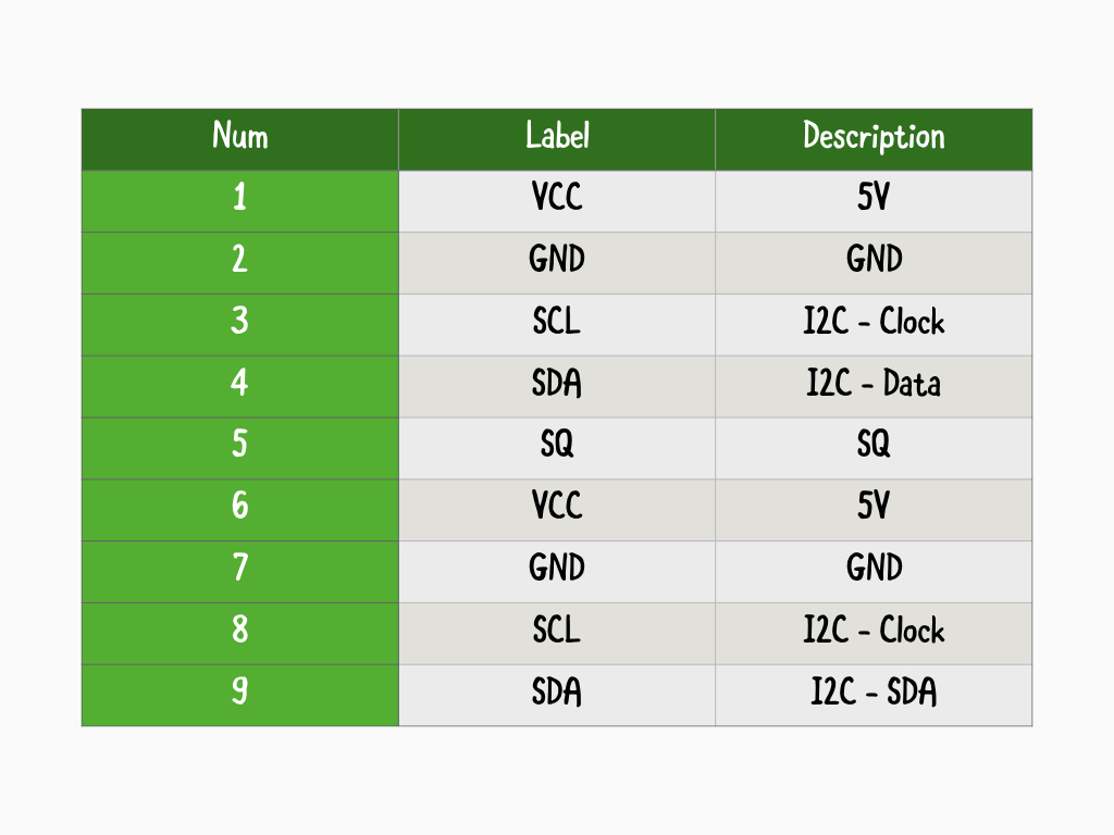
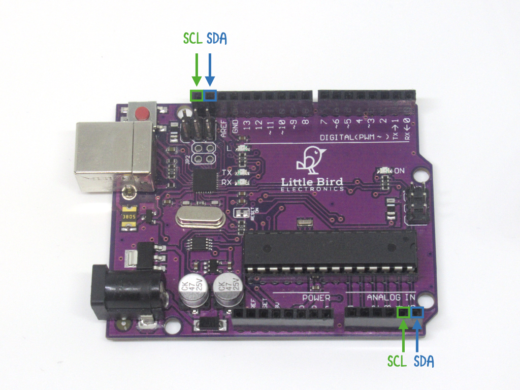
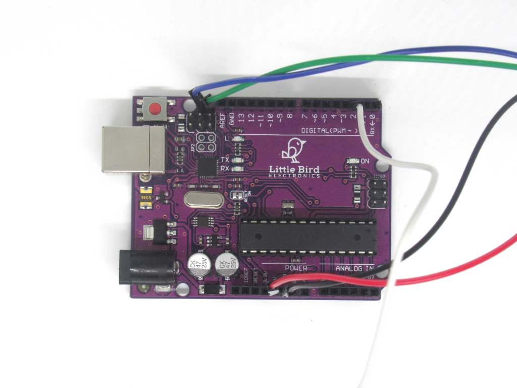
To use the RTC Module with the Arduino, this is done through I²C communication. As shown in the diagram, there are SCL and SDA connections on the module, which can be connected to the Uno R3's SCL and SDA pins, which are the two furthest pins beside AREF as shown in the image. SDA is also connected to A4, and SCL is connected to A5.
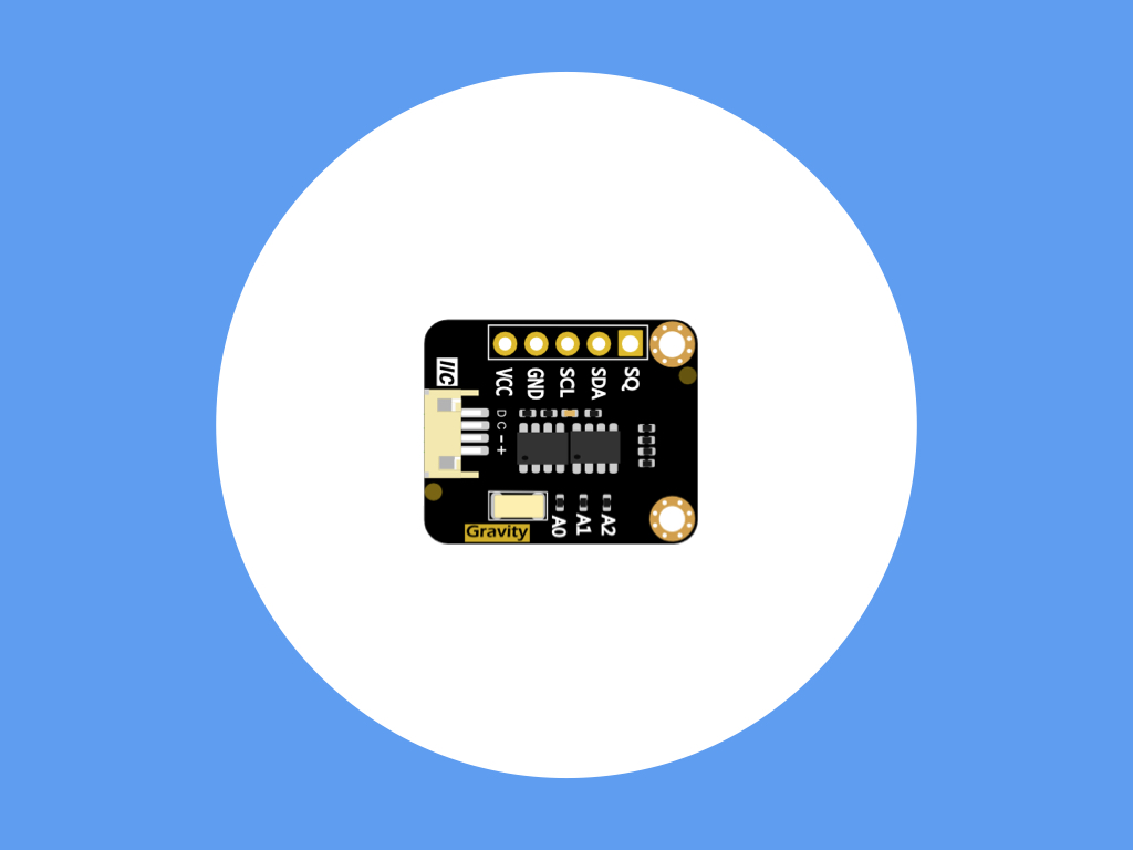
At the heart of this RTC module is the DS1307 chip. This is a serial real-time clock (RTC) that can be used for timekeeping purposes, even when the Arduino or other microcontroller is powered off. The clock operates in either 24-hour or 12-hour format with an AM/PM indicator. This module also has 56 bytes of non-volatile RAM, utilises EERPOM, specifically 4KB ROM to record information related to timekeeping.
In this guide, get started with using the DS1307 RTC Module for time-keeping with the Little Bird Uno - R3.
In this guide, get started with using the DS1307 RTC Module for time-keeping with the Little Bird Uno - R3.
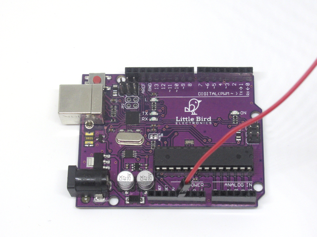
Connect the red M-M jumper wire to 5V on the Little Bird Uno - R3.
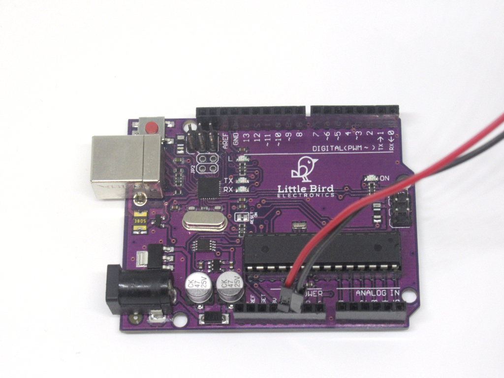
Connect the black M-M jumper wire to GND on the Little Bird Uno - R3.
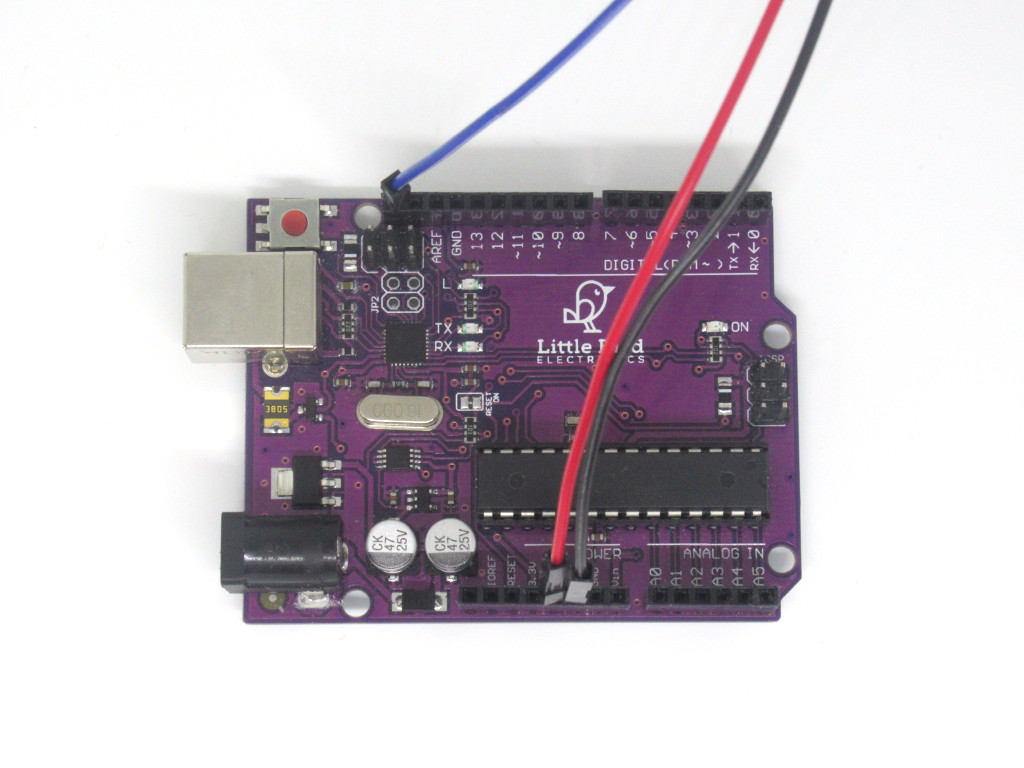
Connect the blue M-M jumper wire to SCL on the Little Bird Uno - R3.
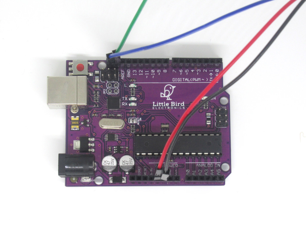
Connect the green M-M jumper wire to SDA on the Little Bird Uno - R3.
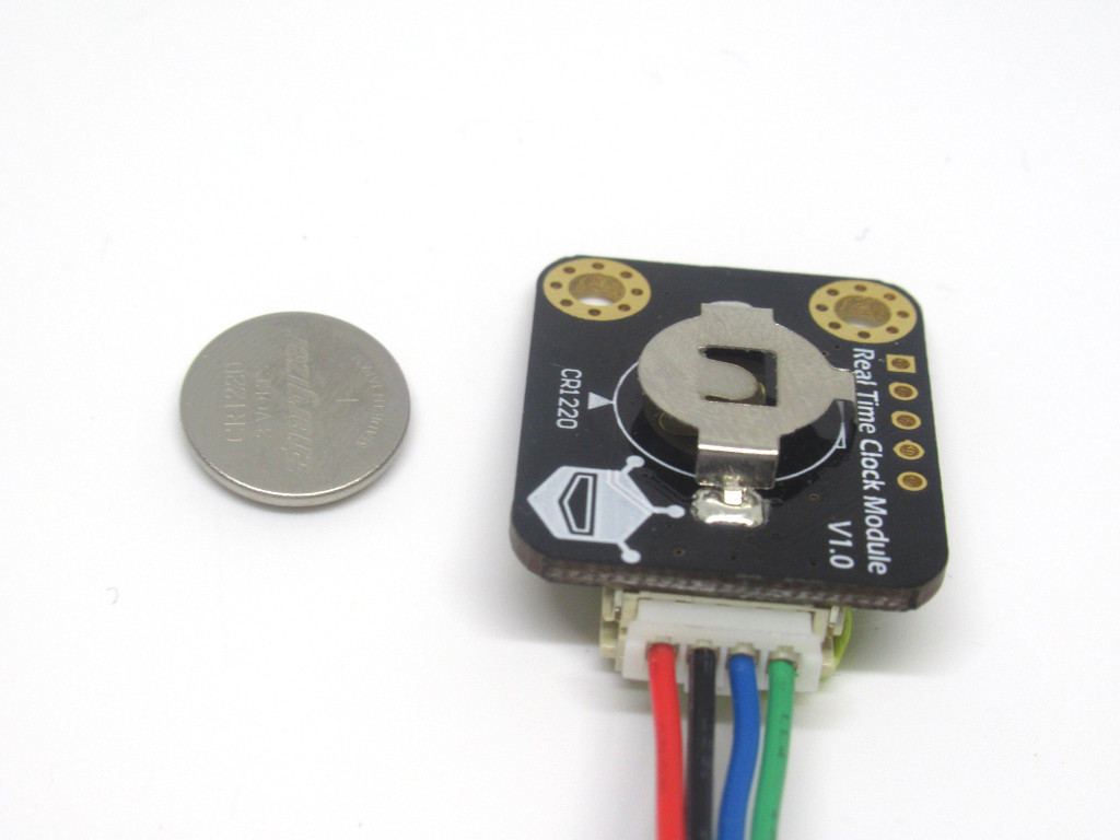
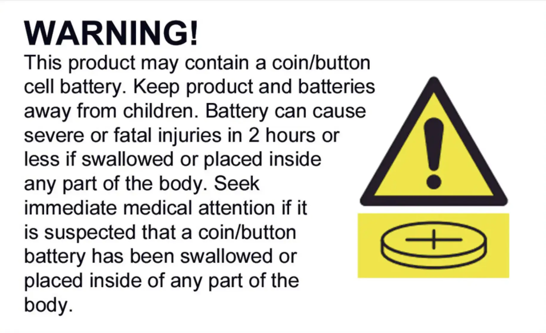
Insert the CR1022 coin cell battery into the RTC Module. With the '+' side facing toward the module as shown.
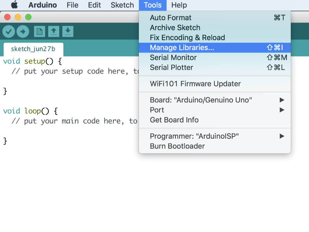
Open up the Arduino IDE and start a new sketch.
Navigate to Tools > Manage Libraries
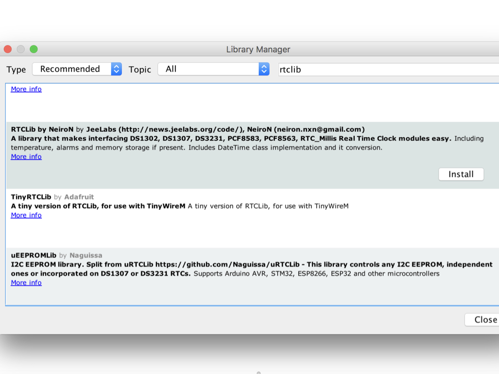
Type 'rtclib' into the search field and look for 'RTCLib'
The DS1307 chip can be used with this commonly-used and reliable Arduino library, which simplifies and hides the actual low-level I²C messages. For more information on I²C , see I²C and Arduino.
Click on the 'Install' button and wait for installation to be complete.
Click the 'Close' button
// Date and time functions using a DS1307 RTC connected via I2C and Wire lib
#include <Wire.h>
#include "RTClib.h"

#if defined(ARDUINO_ARCH_SAMD)
// for Zero, output on USB Serial console, remove line below if using programming port to program the Zero!
   #define Serial SerialUSB
#endif

RTC_DS1307 rtc;

char daysOfTheWeek[7][12] = {"Sunday", "Monday", "Tuesday", "Wednesday", "Thursday", "Friday", "Saturday"};

void setup () {

#ifndef ESP8266
  while (!Serial); // for Leonardo/Micro/Zero
#endif

  Serial.begin(9600);
  if (! rtc.begin()) {
    Serial.println("Couldn't find RTC");
    while (1);
  }

  if (! rtc.isrunning()) {
    Serial.println("RTC is NOT running!");
    // following line sets the RTC to the date & time this sketch was compiled
    //rtc.adjust(DateTime(F(__DATE__), F(__TIME__)));
    // This line sets the RTC with an explicit date & time, for example to set
    // January 21, 2014 at 3am you would call:
    rtc.adjust(DateTime(2019, 06, 27, 16, 43, 0));
  }
}

void loop () {
    DateTime now = rtc.now();

    Serial.print(now.year(), DEC);
    Serial.print('/');
    Serial.print(now.month(), DEC);
    Serial.print('/');
    Serial.print(now.day(), DEC);
    Serial.print(" (");
    Serial.print(daysOfTheWeek[now.dayOfTheWeek()]);
    Serial.print(") ");
    Serial.print(now.hour(), DEC);
    Serial.print(':');
    Serial.print(now.minute(), DEC);
    Serial.print(':');
    Serial.print(now.second(), DEC);
    Serial.println();


    delay(3000);
}
Connect the Little Bird - Uno R3 to the computer via USB type B Cable.
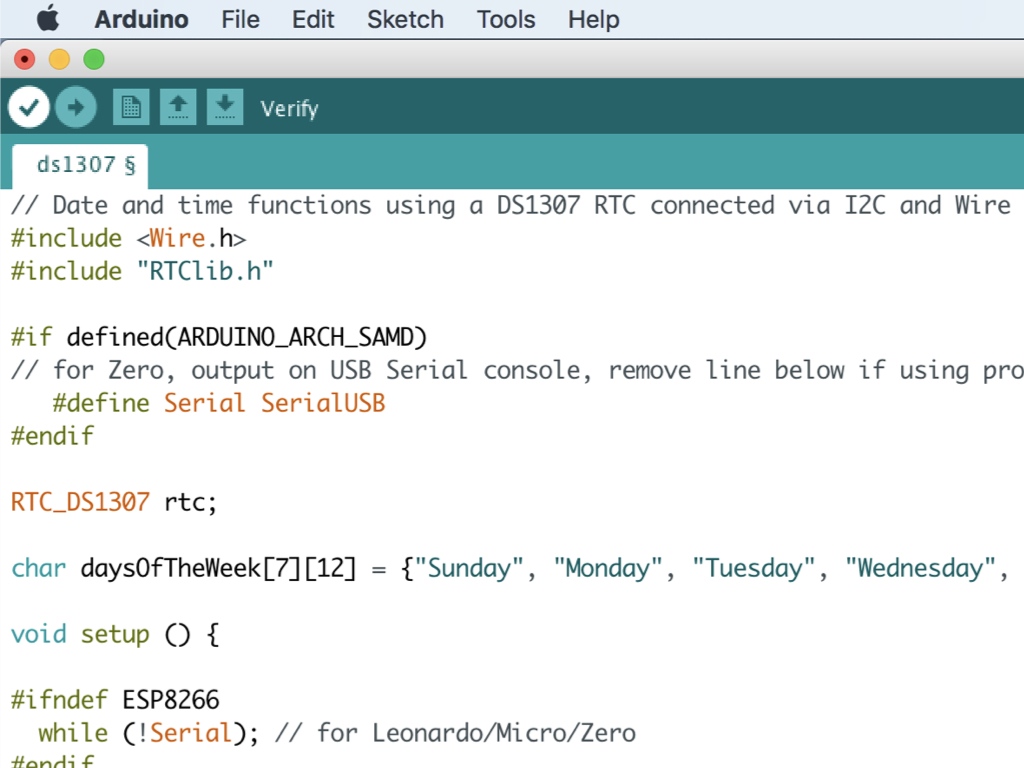
Copy and paste this code into the Arduino IDE.
Change this line of code to the current date and time: rtc.adjust(DateTime(2019, 06, 27, 16, 43, 0));
Navigate to Tools > Board and select 'Arduino/Genuino Uno'
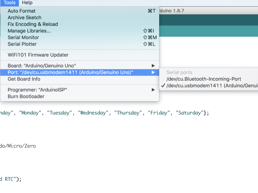
Navigate to Tools > Port and select /dev/cu.usbmodemXXXX (Arduino/Genuino Uno)
In this guide, it is connected to port number 1411, though the port number at your end may differ.
Click on the 'Verify' button.
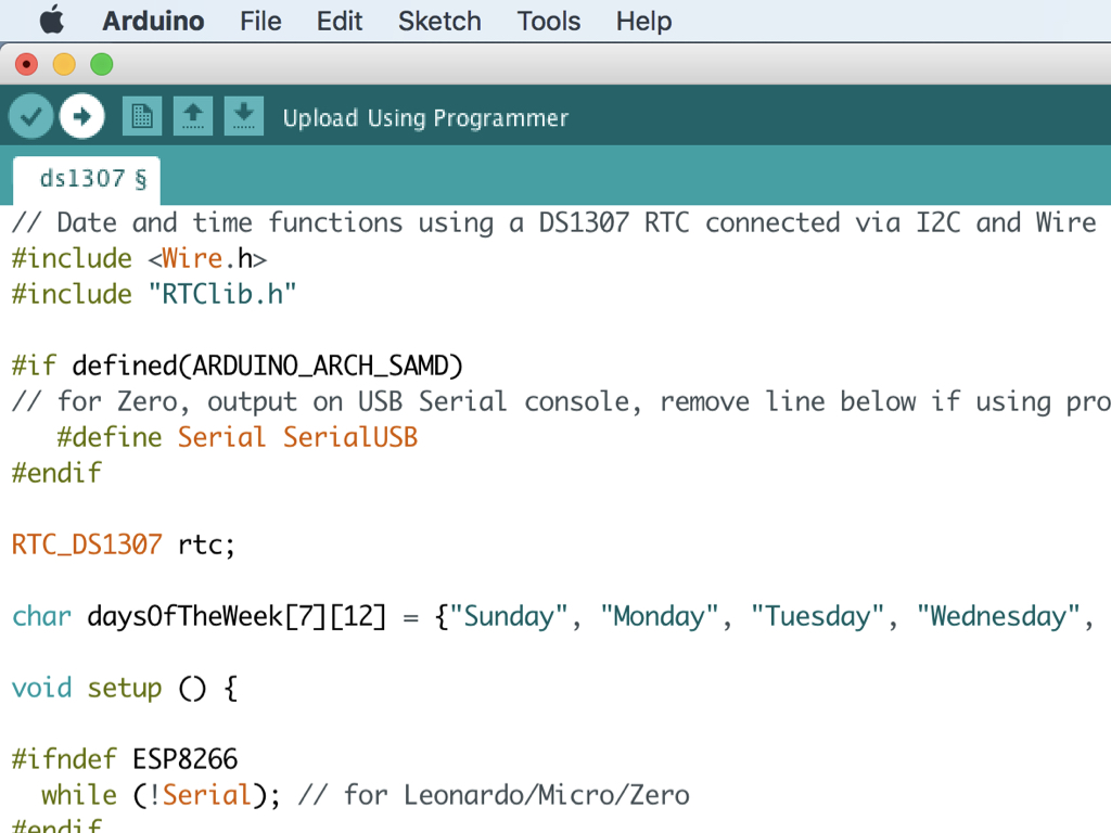
Once verified, click on the 'Upload' button.
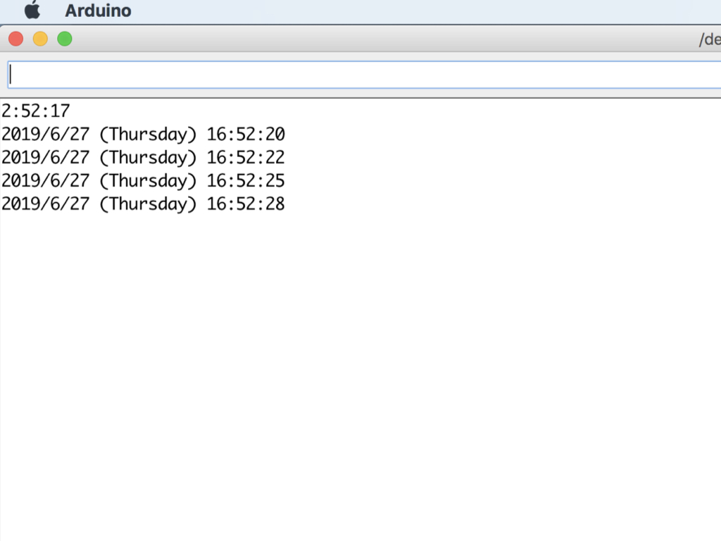
Navigate to Tools > Serial Monitor
Make sure the baud rate is set to 9600, this can be found on the bottom right-hand corner of the serial monitor.
The current time, date, and day of the week will be printed on the serial monitor.
Disconnect the Little Bird Uno - R3 and then reconnect it to the computer. Open up the serial monitor again and time-keeping should be up to date, even though the Uno had been powered off for a while. If not, check to see if the coin cell battery has been inserted the right way.
In this next part of the guide, we'll show you how to use the RTC Module and interrupts to put the Arduino in and out of sleep mode.
Interrupts are events that interrupt the main program flow, and causes the processor to do something else. The Little Bird - Uno R3 has two pins that are capable of generating interrupts, they are digital pin 2 and digital pin 3.
First, insert a jumper wire into digital pin 2 on the Little Bird - Uno R3.
// Date and time functions using a DS1307 RTC connected via I2C and Wire lib
#include <Wire.h>
#include "RTClib.h"
#include <avr/sleep.h>//this AVR library contains the methods that controls the sleep modes
#define interruptPin 2 //Pin we are going to use to wake up the Arduino

RTC_DS1307 rtc;

char daysOfTheWeek[7][12] = {"Sunday", "Monday", "Tuesday", "Wednesday", "Thursday", "Friday", "Saturday"};

void setup () {
  pinMode(LED_BUILTIN, OUTPUT); //We use the led on pin 13 to indecate when Arduino is asleep
  pinMode(interruptPin, INPUT_PULLUP); //Set pin d2 to input using the built-in pullup resistor
  digitalWrite(LED_BUILTIN, HIGH); //turn built-in LED on
  Serial.begin(9600);
  if (! rtc.begin()) {
    Serial.println("Couldn't find RTC");
    while (1);
  }

  if (! rtc.isrunning()) {
    Serial.println("RTC is NOT running!");
    // following line sets the RTC to the date & time this sketch was compiled
    rtc.adjust(DateTime(F(__DATE__), F(__TIME__)));
    // This line sets the RTC with an explicit date & time, for example to set
    // January 21, 2014 at 3am you would call:
    //rtc.adjust(DateTime(2019, 06, 27, 20, 30, 0));
  }
}

void loop () {
  DateTime now = rtc.now();
  Serial.print(now.hour(), DEC);
  Serial.print(':');
  Serial.print(now.minute(), DEC);
  Serial.print(':');
  Serial.print(now.second(), DEC);
  Serial.println();
  if (now.hour() == 20) {
    delay(5000); //wait 5 seconds before going to sleep
    Going_To_Sleep();
  }
}

void Going_To_Sleep() {
  sleep_enable();//Enabling sleep mode
  attachInterrupt(0, wakeUp, LOW);//attaching a interrupt to pin d2
  set_sleep_mode(SLEEP_MODE_PWR_DOWN);//Setting the sleep mode, in our case full sleep
  digitalWrite(LED_BUILTIN, LOW); //turn LED off
  delay(1000); //wait a second to allow the led to be turned off before going to sleep
  sleep_cpu();//activating sleep mode
  Serial.println("just woke up!");//next line of code executed after the interrupt
  digitalWrite(LED_BUILTIN, HIGH); //turn LED on
}

void wakeUp() {
  Serial.println("Interrrupt Fired");//Print message to serial monitor
  sleep_disable();//Disable sleep mode
  detachInterrupt(0); //Removes the interrupt from pin 2;
}
When the Arduino is put to sleep, it turns off power-consuming components, thereby reducing power consumption. In this sketch, we've set the sleep mode to SLEEP_MODE_PWR_DOWN,the highest power saving mode.
There are five different sleep modes. In order of lowest power saving to highest power saving: SLEEP_MODE_IDLE, SLEEP_MODE_ADC, SLEEP_MODE_PWR_SAVE, SLEEP_MODE_STANDBY, and SLEEP_MODE_PWR_DOWN.
There are five different sleep modes. In order of lowest power saving to highest power saving: SLEEP_MODE_IDLE, SLEEP_MODE_ADC, SLEEP_MODE_PWR_SAVE, SLEEP_MODE_STANDBY, and SLEEP_MODE_PWR_DOWN.
Copy and paste the following code into the Arduino IDE.
First, we have included the <avr/sleep.h> library, an AVR library that contains the methods needed to control the sleep modes.
In void setup(), we've set the pin modes for the built-in LED, and the interruptPin (which is the pin we'll use to wake up the Arduino, in this case it would be digital pin 2). We also turned the built-in LED ON.
In the main loop() function, we've programmed it so that as long as time is within the 20:00 or 8PM range, a delay of 5 seconds happens before the Go_To_Sleep() function is called.
Adjust the conditional statement to the current hour: if (now.hour() == 20) {
In the Go_To_Sleep() function, sleep mode is first enabled, without which it would not be possible to set the Arduino to sleep mode. Next, an interrupt is attached to digital pin 2.
Then we set the sleep mode to SLEEP_MODE_PWR_DOWN. To get some visual indication on whether the Arduino is awake or asleep, we've used the built-in LED.
Next, sleep mode is activated with sleep_cpu();
The code then halts here, until the interrupt is called. When the interrupt is called, the Interrupt Service Routine (ISR) which is the function named wakeUp, is called.
So how does the Arduino wake up from sleep mode? This is done by attaching the other end of the jumper wire to a GND pin, which will pull digital pin 2 to LOW. This triggers the interrupt. Finally, sleep mode is disabled and the interrupt is removed from digital pin 2.
The built-in LED will come back on, so remove the jumper wire from GND. The Arduino will then go back to sleep after 5 seconds, and you can plug the jumper wire back into GND to awake the Arduino again.
Upload the code to the Little Bird - Uno R3. The built-in LED should light up before going to sleep after 5 seconds. Plug in the other end of the jumper wire to a GND pin to wake the Arduino.