Macro Keypad with ATmega32u4
Create your own programmable eight button macro keypad!
Written By: Cherie Tan
Difficulty
Medium
Steps
18
The ATmega32u4 found on the Teensy board is capable of emulating a USB HID device such as a keyboard or mouse.
In this guide, learn to use the Bounce.h library to emulate a USB HID device.
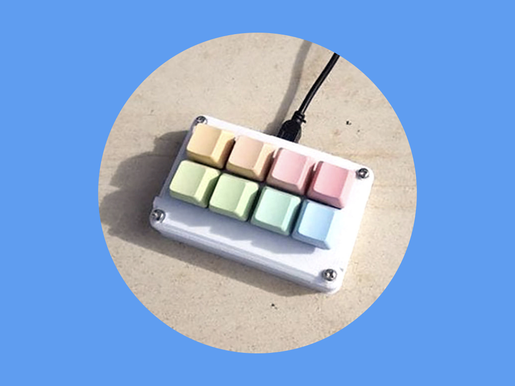
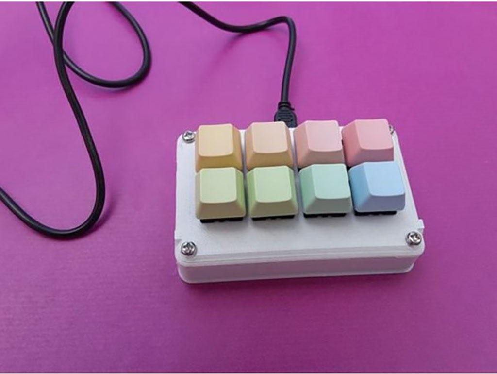
Complete this guide to create your own programmable eight-button macro keypad.
In this guide, learn to use the Bounce.h library to emulate a USB HID device.
Complete this guide to create your own programmable eight-button macro keypad.
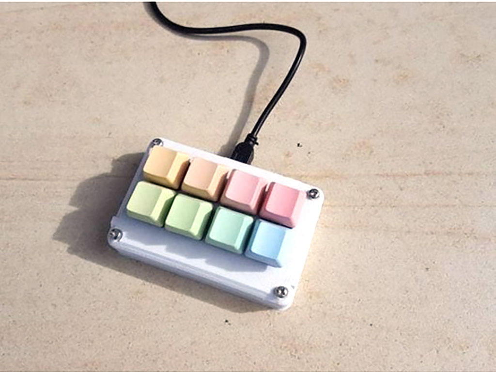
The ATmega32u4 found on the Teensy board is capable of emulating a USB HID device such as a keyboard or mouse. In this guide, we'll show you how to create your own programmable macro keypad with the Teensy, Cherry MX Red Switches, a handful of jumper wires, and a custom 3D printed case.
Got an Arduino Pro Micro lying around? The Arduino Pro Micro also has an ATmega32u4, with a full-speed uSB transceiver, so you may also use it to create a macro keypad!
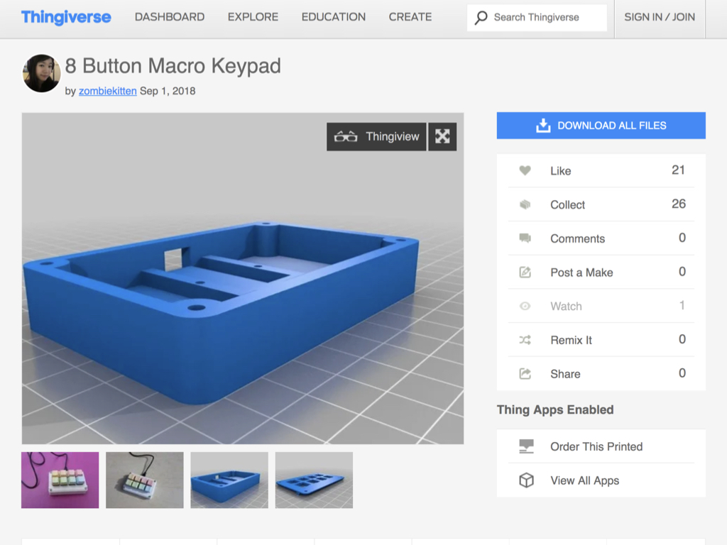
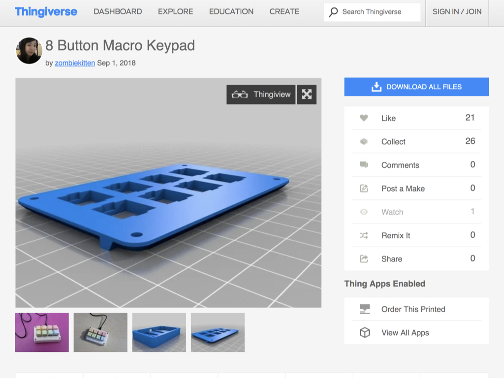
First, head to Thingiverse to download the STL files for the 8-button macro keypad case.
There are two parts to the case. Printing it in either PLA or ABS will both work fine.


After placing the eight Cherry Red MX switches into the front panel of the case, solder jumper wires along the first row of switches.
It won't matter which leg of a switch is used, but to keep it looking a little more organised, solder wires along the legs that are on the same side.

Solder jumper wires along the second row of switches.
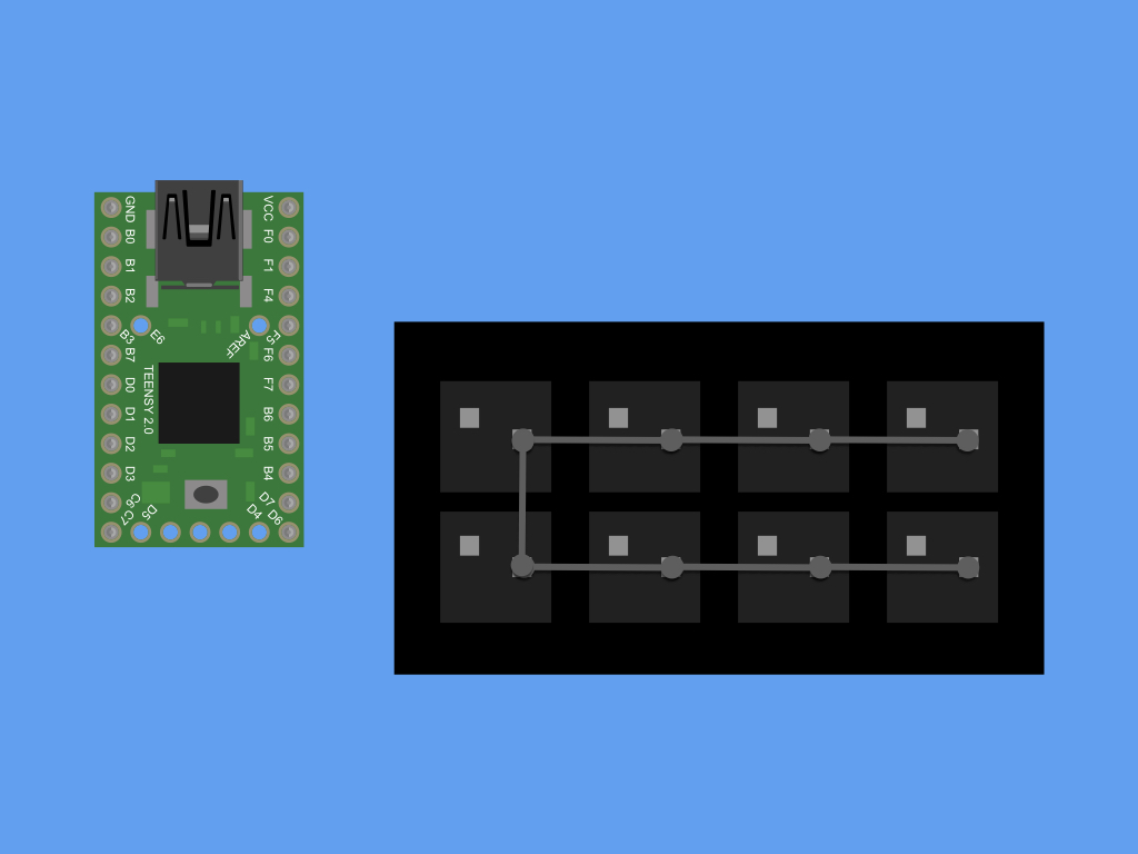
Solder a jumper wire, connecting the first row of soldered pins to the second row.


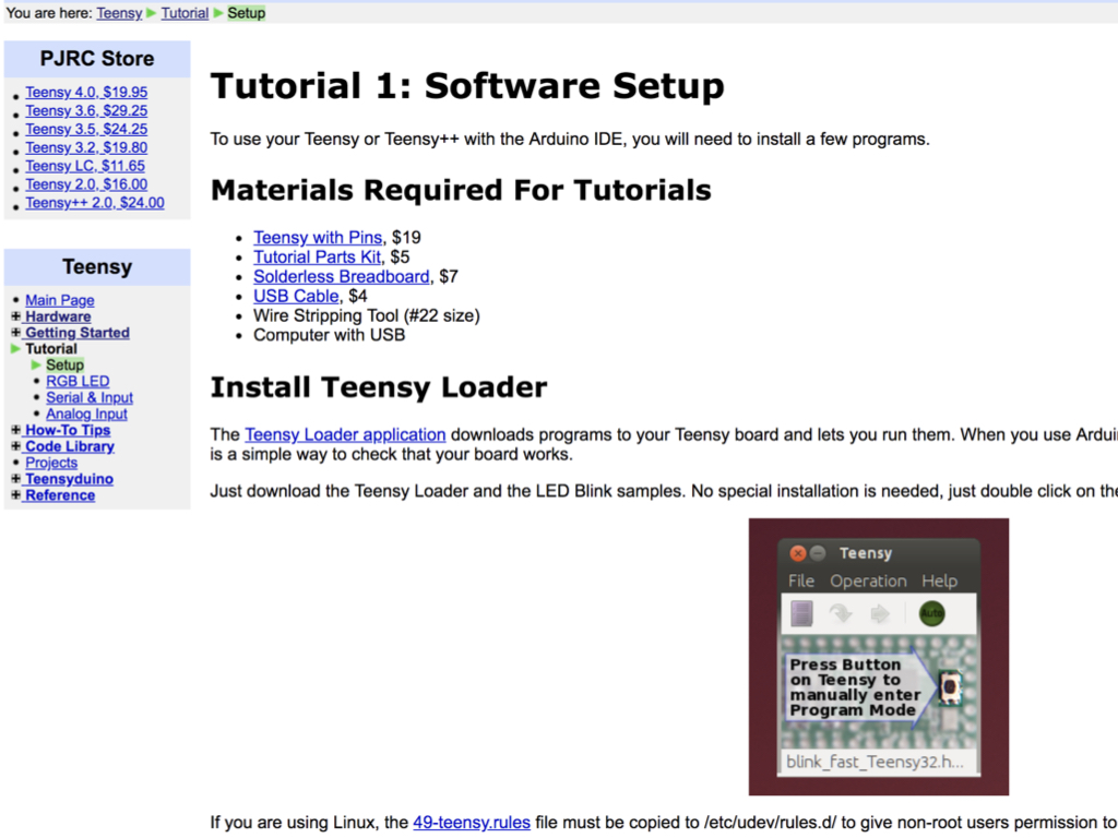
Before we can upload a sketch to the Teensy board, a few programs will need to be installed such as the Teensy Loader application. Follow the instructions here.
Combine the front panel and bottom part of the case together with four phillips head screws.
Connect a mini USB cable to the Teensy, and connect its USB end to the computer.
/* Buttons to USB Keyboard Example
   You must select Keyboard from the "Tools > USB Type" menu
   This example code is in the public domain.
*/

#include <Bounce.h>

// Create Bounce objects for each button.  The Bounce object
// automatically deals with contact chatter or "bounce", and
// it makes detecting changes very simple.
Bounce button0 = Bounce(1, 50);
Bounce button1 = Bounce(2, 50);  // 10 = 10 ms debounce time
Bounce button2 = Bounce(3, 50);  // which is appropriate for
Bounce button3 = Bounce(4, 50);  // most mechanical pushbuttons
Bounce button4 = Bounce(5, 50);
Bounce button5 = Bounce(6, 50);  // if a button is too "sensitive"
Bounce button6 = Bounce(20, 50);  // to rapid touch, you can
Bounce button7 = Bounce(21, 50);  // increase this time.


void setup() {
  // Configure the pins for input mode with pullup resistors.
  // The pushbuttons connect from each pin to ground.  When
  // the button is pressed, the pin reads LOW because the button
  // shorts it to ground.  When released, the pin reads HIGH
  // because the pullup resistor connects to +5 volts inside
  // the chip.  LOW for "on", and HIGH for "off" may seem
  // backwards, but using the on-chip pullup resistors is very
  // convenient.  The scheme is called "active low", and it's
  // very commonly used in electronics... so much that the chip
  // has built-in pullup resistors!
  pinMode(1, INPUT_PULLUP);
  pinMode(2, INPUT_PULLUP);
  pinMode(3, INPUT_PULLUP);
  pinMode(4, INPUT_PULLUP);
  pinMode(5, INPUT_PULLUP);
  pinMode(6, INPUT_PULLUP);
  pinMode(20, INPUT_PULLUP);  // Teensy++ LED, may need 1k resistor pullup
  pinMode(21, INPUT_PULLUP);
}

void loop() {
  // Update all the buttons.  There should not be any long
  // delays in loop(), so this runs repetitively at a rate
  // faster than the buttons could be pressed and released.
  button0.update();
  button1.update();
  button2.update();
  button3.update();
  button4.update();
  button5.update();
  button6.update();
  button7.update();

  // Check each button for "falling" edge.
  // Type a message on the Keyboard when each button presses
  // Update the Joystick buttons only upon changes.
  // falling = high (not pressed - voltage from pullup resistor)
  //           to low (pressed - button connects pin to ground)
  if (button0.fallingEdge()) {
    //Set button 0  to
    Keyboard.press(KEY_LEFT_CTRL);
    Keyboard.press(KEY_D);
    delay(100);
    Keyboard.releaseAll();
  }
  if (button1.fallingEdge()) {
    Keyboard.press(KEY_LEFT_CTRL);
    Keyboard.press(MODIFIERKEY_RIGHT_SHIFT);
    Keyboard.press(KEY_EQUAL);
    delay(100);
    Keyboard.releaseAll();
  }
  if (button2.fallingEdge()) {
     //Set button 2 to
    Keyboard.press(KEY_LEFT_CTRL);
    Keyboard.press(KEYPAD_0);
    delay(100);
    Keyboard.releaseAll();
  }
  if (button3.fallingEdge()) {
    //Set button 3 to
    Keyboard.press(KEY_END);
    delay(100);
    Keyboard.releaseAll();
  }
  if (button4.fallingEdge()) {
    Keyboard.press(KEY_LEFT_CTRL);
    Keyboard.press(KEY_Z);
    delay(100);
    Keyboard.releaseAll();
  }
  if (button5.fallingEdge()) {
    Keyboard.press(MODIFIERKEY_RIGHT_SHIFT);
    Keyboard.press(KEYPAD_5);
    delay(100);
    Keyboard.releaseAll();
  }
    if (button6.fallingEdge()) {
    Keyboard.press(KEY_PAGE_UP);
    delay(100);
    Keyboard.releaseAll();
  }
    if (button7.fallingEdge()) {
    Keyboard.press(KEY_PAGE_DOWN);
    delay(100);
    Keyboard.releaseAll();
  }
}
Copy and paste the following code into the Arduino IDE.
Make sure Tools > USB Type is selected.
Click on the Verify button.
Click on the Upload button.
When called, Keyboard.press() functions as if a key were pressed and held on your keyboard.
Keyboard.releaseAll() lets go of all keys currently pressed.
Keyboard.releaseAll() lets go of all keys currently pressed.
You may not want a button to be programmed as say LEFT_CTRL + Z. For a complete table of Key Codes, see here.
Your build is now complete. As a next step, you may want to create one with more buttons, check out the 16 button variation on Thingiverse.