LEDs with Arduino
Fade, Flicker and Twinkle.
Written By: Cherie Tan

Difficulty
Easy
Steps
8
LEDs (light emitting diodes) can be found nearly everywhere, especially in many Arduino projects.
In this guide, you will learn how to use an LED with the Little Bird Uno R3 board by connecting them using a mini breadboard, some jumper wires and a resistor.
Learning to do so will enable you to use LEDs in your own Arduino projects that may require illumination or indication.
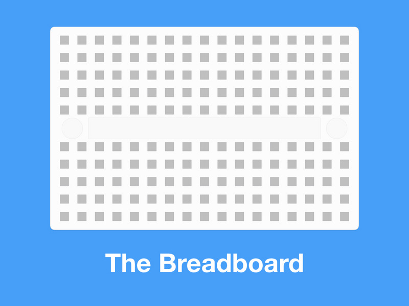
We've provided you with a mini breadboard. These breadboards have conductive material that connects the holes (known as points) inside the breadboard.
The breadboard points are connected to each other vertically, with a trough in the middle that enables more prototyping area.
The conductive material (and electrically joined points) are shown in this diagram in gold.
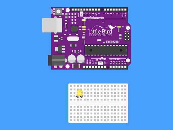
Insert your LED into your breadboard so that the cathode (short leg) is on the left-hand side and the anode (long leg) is on the right-hand side.

Insert your resistor so that one of it's legs vertically in line with the LED's anode (long leg).
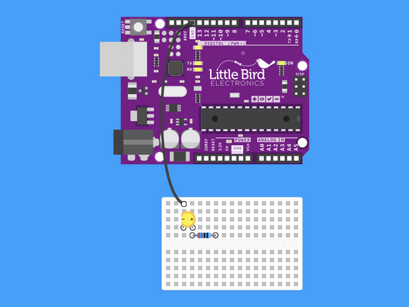
Run a jumper wire from an Arduino Ground Pin (GND) to the LED's cathode

Run another jumper wire from pin 9 so that it's vertically in line with the resistor's other leg.
The resistor is the longer wire with a bead like middle.
void setup() {
  // initialize digital pin 9 as an output.
  pinMode(9, OUTPUT);
}

// the loop function runs over and over again forever
void loop() {
  digitalWrite(9, HIGH);   // turn the LED on (HIGH is the voltage level)
  delay(1000);                // wait for a second
  digitalWrite(9, LOW);    // turn the LED off by making the voltage LOW
  delay(1000);              // wait for a second
}
This code will turn an LED on and off just like we did with the onboard LED on Day 1. The only difference in this code is that we've changed the pin on which the LED will blink from Digital Pin 13 to Digital Pin 9.
Copy and paste the code into your Arduino Software.
Upload the code by clicking on the arrow button.
Remember HIGH or 1 is on and LOW or 0 is off.
The delay will be the amount of time the light stays on or off.
int ledPin = 9;    // LED connected to digital pin 9

void setup() {
  // nothing happens in setup
}

void loop() {
  // fade in from min to max in increments of 5 points:
  for (int fadeValue = 0 ; fadeValue <= 255; fadeValue += 5) {
    // sets the value (range from 0 to 255):
    analogWrite(ledPin, fadeValue);
    // wait for 30 milliseconds to see the dimming effect
    delay(30);
  }

  // fade out from max to min in increments of 5 points:
  for (int fadeValue = 255 ; fadeValue >= 0; fadeValue -= 5) {
    // sets the value (range from 0 to 255):
    analogWrite(ledPin, fadeValue);
    // wait for 30 milliseconds to see the dimming effect
    delay(30);
  }
}
The delay will be the amount of time the light stays on or off
This code will turn an LED on and off just like we did with the onboard LED on Day 1. The only difference in this code is that we've changed the pin on which the LED will blink from Digital Pin 13 to Digital Pin 9.
Copy and paste the code into your Arduino Software
Upload the code by clicking on the arrow button
Remember HIGH or 1 is on and LOW or 0 is off
// Create a new variable called ledPin which will hold the value 9.
// We're using the value 9 because our LED is connected to Digital Pin 9.
int ledPin = 9;

// This is the void setup() function.
// Code within this function runs only once.
void setup()
{
  pinMode(ledPin, OUTPUT); // Make Digital Pin 9 an OUTPUT
}

void loop() {

  // Set the brightness of the LED to a random value.
  analogWrite(ledPin, random(200)+150);

  // Randomly delay for a period of time between 0 and 0.3 seconds.
  delay(random(300));
}
This code will demonstrate how to make your LED flicker like a candle. This is a really simple special effect you can add to models or other installations.
Copy and paste the code into your Arduino Software.
Upload the code by clicking on the arrow button.