Interrupts and Arduino
Learn about interrupts and how to use it in your sketches
Written By: Cherie Tan
Difficulty
Medium
Steps
16
Imagine constantly checking on the status of something, and not being able to do anything else. In computer terms, this constant process of checking on the state of something is known as polling. In the context of an Arduino project, this may be checking on the state of a sensor. With the polling approach, the processor is engaged in this particular task, and so cannot perform any other tasks. There is another approach - using interrupts! By using interrupts, the processor is free to do multiple tasks while not missing any important events or input from the sensor.
In this guide, learn about the two types of interrupts, hardware interrupts and software interrupts.
Complete this guide to gain a better understanding on how to use interrupts in your sketches.
In this guide, learn about the two types of interrupts, hardware interrupts and software interrupts.
Complete this guide to gain a better understanding on how to use interrupts in your sketches.
What are interrupts? As its name suggests, it interrupts whatever the processor is doing. More specifically, interrupts allow the microcontroller to respond to an external signal, such as the change in state of a sensor, while performing another task. When the interrupt happens, the processor gives it a higher priority, takes immediate notice, and runs the interrupt service routine (ISR) which is a small chunk of code. After which, the sketch continues from the point that it was interrupted and resumes its normal operation.
Why are interrupts important? Normally, the microcontroller constantly checks the state of a device or sensor. This constant process of checking the state of a device on whether it needs service from the processor is known as polling. With this polling approach, the processor is engaged in this particular task and so it cannot perform any other tasks.
For example, using a sound sensor without interrupts in your program would mean that the processor would need to constantly poll to catch a sound (for instance, a clap or click) when they occurred.
With interrupts, this frees up the microcontroller to do multiple tasks while not missing any input from the sensor.
With interrupts, this frees up the microcontroller to do multiple tasks while not missing any input from the sensor.
In this guide, learn about the two types of interrupts, hardware interrupts and software interrupts.
The first type of interrupt is the hardware interrupt.
Why use them? Pulses from some sensors may be active for only a very short time (i.e. a millionth of a second) and easily missed, even more so If there were many tasks for the processor to execute within the loop function, as well as delays.
To counter this problem, these interrupts are triggered from hardware rather than from software, regardless of what the microcontroller may be doing in software. As such, when there is a change in the state of a device or sensor, the microcontroller responds accordingly.
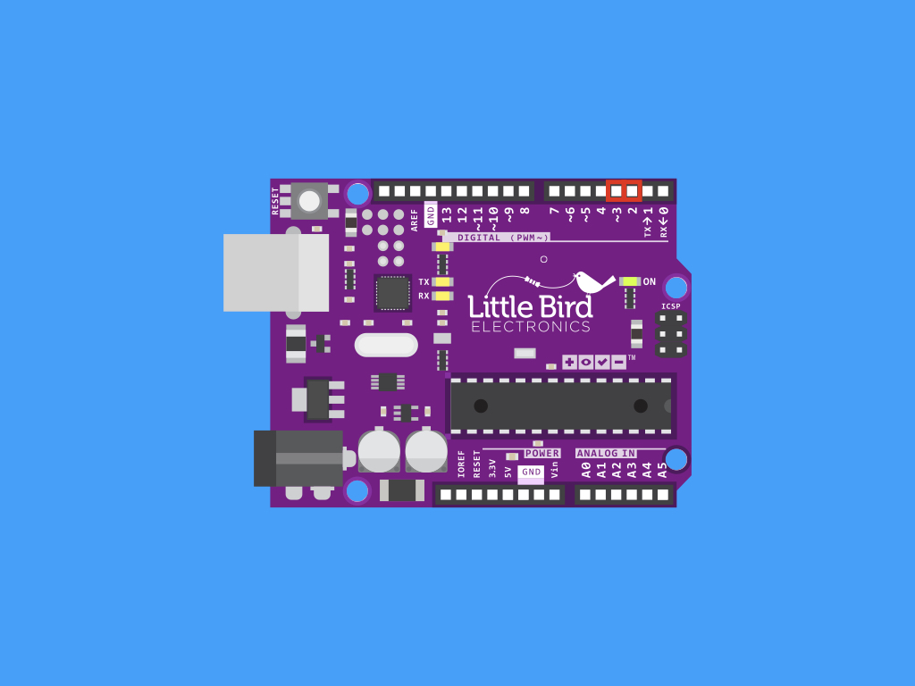
There are two pins that can be used as hardware interrupts on the Little Bird Uno R3. These are digital pin 2 and digital pin 3, which are referred to as interrupt0 and interrupt1, also known as INT0 and INT1.
In the first part of this guide, we'll show you how to utilise hardware interrupts. We'll connect the Little Bird Uno R3 with a push button on a breadboard.

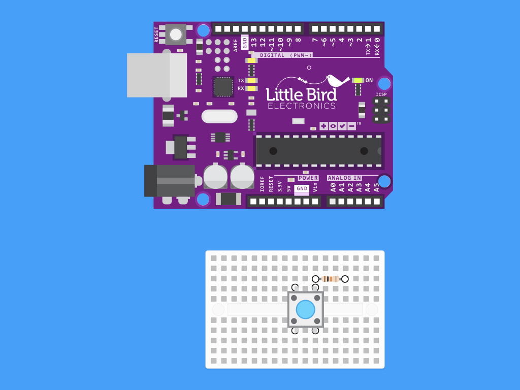
Insert your resistor so that one leg is in line with the other end of the push button.
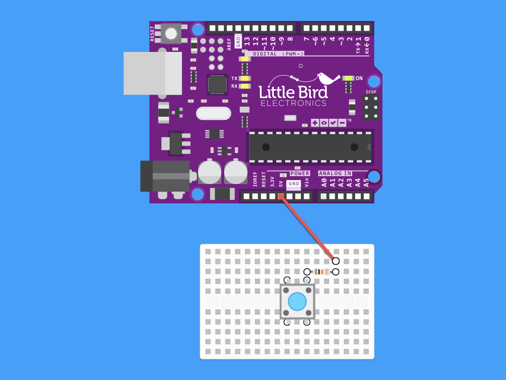
Connect a red jumper wire from one end of the resistor (not in line with the push button leg) to 5V on the Little Bird Uno R3.

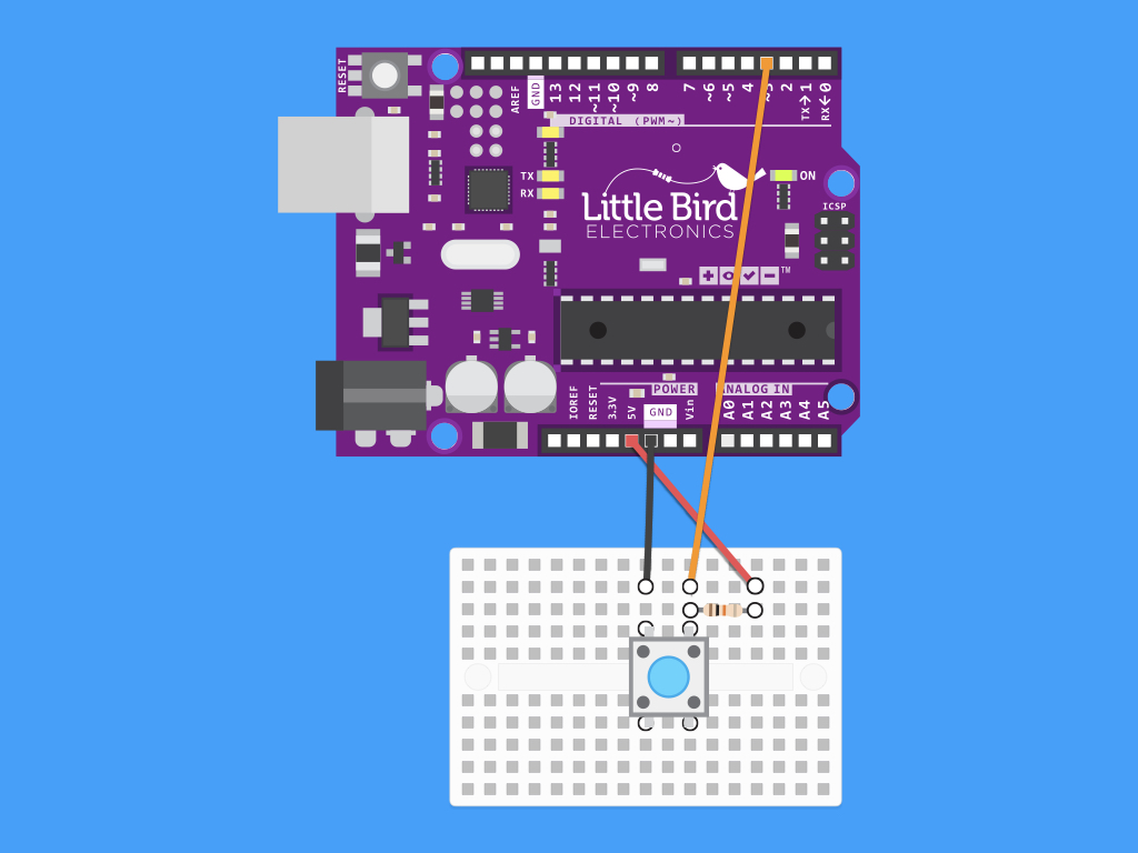
Connect a jumper wire where the resistor and push button meet, and insert the other end to digital pin 3 on the Little Bird Uno R3.
const unsigned int buttonPin = 3;
const unsigned int ledPin = 13;

int buttonState = 0;
int oldButtonState = LOW;
int ledState = LOW;

void setup() {
  pinMode(ledPin, OUTPUT);
  pinMode(buttonPin, INPUT_PULLUP);
}

void loop() {
  buttonState = digitalRead(buttonPin);

  if (buttonState != oldButtonState &&
      buttonState == HIGH)
  {
    ledState = (ledState == LOW ? HIGH : LOW);
    digitalWrite(ledPin, ledState);
    delay(50);
  }
  oldButtonState = buttonState;
}
Before we write a sketch that uses a hardware interrupt, let's look at an example without one.
Upload this code to the Little Bird Uno R3.
This sketch uses polling, where the processor is continually engaged with checking for the state of the button in the loop function.
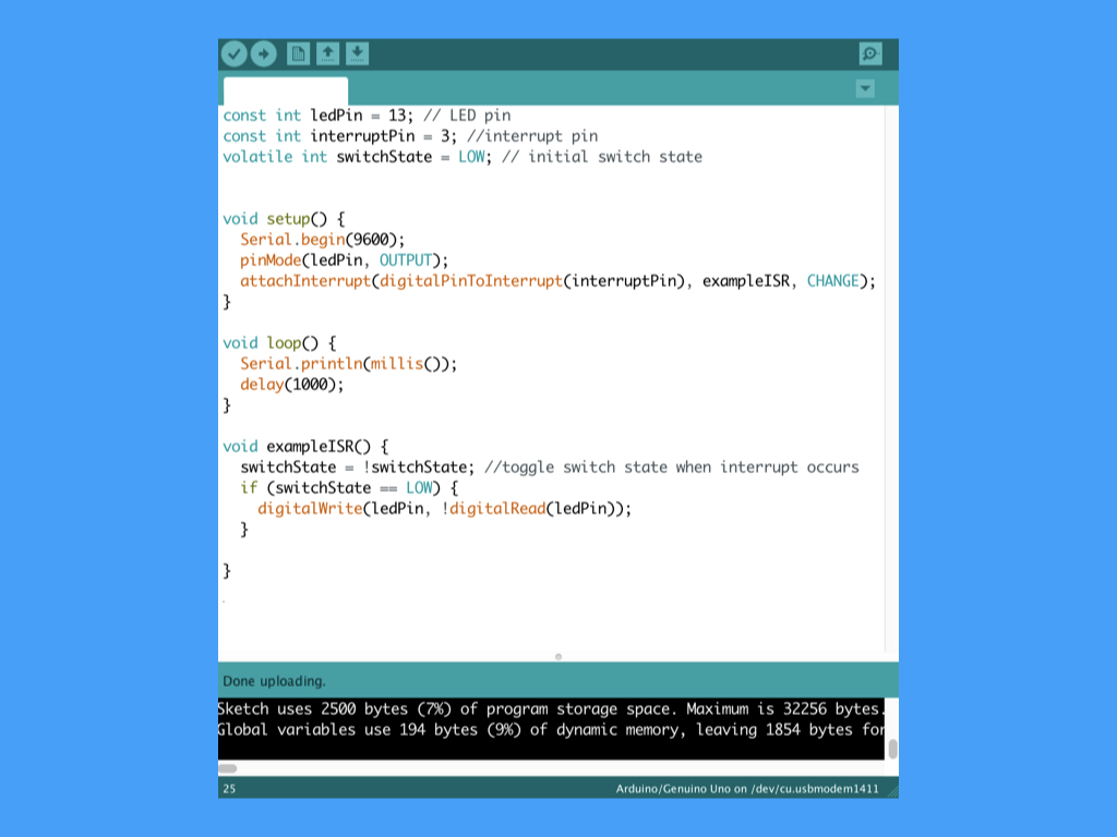
const int ledPin = 13; // LED pin
const int interruptPin = 3; //interrupt pin
volatile int switchState = LOW; // initial switch state


void setup() {
  Serial.begin(9600);
  pinMode(ledPin, OUTPUT);
  attachInterrupt(digitalPinToInterrupt(interruptPin), exampleISR, CHANGE);
}

void loop() {
  Serial.println(millis());
  delay(1000);
}

void exampleISR() {
  switchState = !switchState; //toggle switch state when interrupt occurs
  if (switchState == LOW) {
    digitalWrite(ledPin, !digitalRead(ledPin));
  }

}
Replace the previous sketch with the following, and upload it to the Little Bird Uno R3.
This time, when the button is pressed, it triggers the hardware interrupt. The processor then pauses what it is doing, and the interrupt service routine (ISR) in this case, Example() is applied. The LED then turns off momentarily as long as the button is pressed.
Notice that we declared the variable, buttonState as 'volatile'.
Although the sketch may work if you do not use volatile, it is best practice to use it when working with interrupt service routines.
This is because, declaring a variable as volatile causes the compiler to generate code that always reads the variable from RAM, and not from a storage register, which is a temporary memory location where program variables are stored and manipulated. In some conditions, the value for the variable stored in the temporary memory location can be inaccurate. Hence, by using volatile, this better guarantees that the variable is updated correctly.
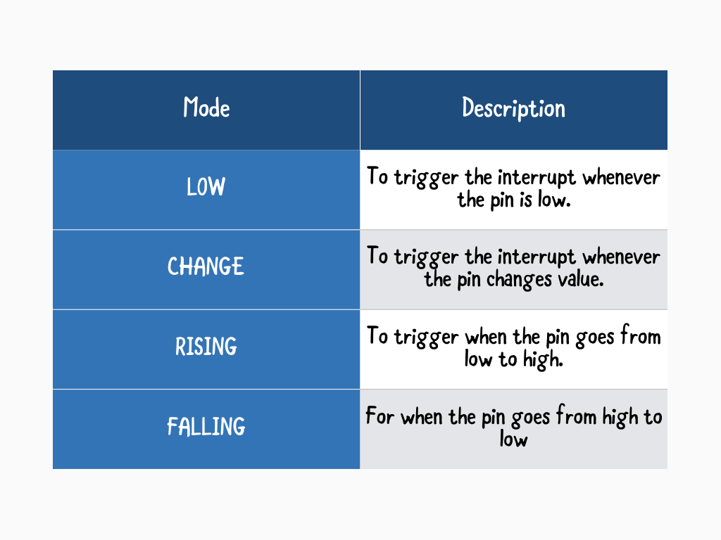
There are 4 interrupt modes: LOW, RISING, FALLING, and CHANGE. In the previous sketch, we've used CHANGE. So the interrupt is triggered whenever the pin changes in either direction, from LOW to HIGH or HIGH to LOW.
The Due, Zero and MKR1000 boards also allow a HIGH mode.
const int ledPin = 13; // LED pin
const int interruptPin = 3; //interrupt pin
volatile int switchState = LOW; // initial switch state


void setup() {
  Serial.begin(9600);
  pinMode(interruptPin, INPUT_PULLUP);
  pinMode(ledPin, OUTPUT);
  attachInterrupt(digitalPinToInterrupt(interruptPin), exampleISR, CHANGE);
}

void loop() {
  Serial.println(millis());
  delay(1000);
}

void exampleISR() {
  switchState = !switchState; //toggle switch state when interrupt occurs
  if (switchState == LOW) {
    digitalWrite(ledPin, !digitalRead(ledPin));
  }

}
Additionally, you may wish to use the internal pull-up resistor in the Arduino board by enabling it in the setup function. This way, you could skip adding a pull-up resistor to the button altogether.
Simply use INPUT_PULLUP in the setup function as shown.
Simply use INPUT_PULLUP in the setup function as shown.
// Normal code
noInterrupts();
// Time critical code
interrupts();
// Normal code
Interrupts are enabled in a sketch by default. However, in certain areas of code, you may want to disable interrupts. To do so, use noInterrupts(). To re-enable it, use interrupts().
Some functions will not work while interrupts are disabled, and incoming communication may be ignored.
Keep the interrupt service routine as short as possible, this is because while the ISR is running, everything else is put on hold.
While ISR is running, no other interrupts can take place! This often means, other libraries that have their own ISRs will not work while the ISR is active.
For example, the delay function and millis function uses interrupts, so they won't work when used in an ISR. However, you can use delayMicroseconds().
For example, the delay function and millis function uses interrupts, so they won't work when used in an ISR. However, you can use delayMicroseconds().
Also, the code in loop() is there so that something is interrupted when you press the button. If an empty loop() was used instead, generally, the compiler will optimise it away.
const int LED = 13; //built-in LED pin
unsigned long previousMillis = 0; //time that the LED state was last changed

int ledState = LOW;

void setup() {
  pinMode(LED, OUTPUT); //sets built-in LED as OUTPUT
}

void loop() {

  if (millis() - previousMillis > 3000) { //3000ms or 3 seconds since last event
    ledState = (ledState == LOW ? HIGH : LOW);
    digitalWrite(LED, ledState);
    previousMillis = millis(); // save time that event last occurred
  }
}
Besides triggering interrupts through hardware, it is also possible to trigger interrupts through software.
Previously, we've already scheduled timed events through the use of the delay() function. However, delay() pauses the entire program. The disadvantage then is that virtually all microcontroller activity is stopped.
Instead, timed events can be scheduled with the millis() function.
Previously, we've already scheduled timed events through the use of the delay() function. However, delay() pauses the entire program. The disadvantage then is that virtually all microcontroller activity is stopped.
Instead, timed events can be scheduled with the millis() function.
millis() is a built-in method of the Arduino library, and it returns the number of milliseconds that the sketch has been running, or since the board has been powered up. It starts at zero milliseconds each time the board is reset, and is incremented each millisecond by a CPU hardware counter.
An unsigned long variable is created to store the last time that the LED was updated. You should use unsigned long for variables that hold time, as the value quickly becomes too large for an int to store.
Copy and paste this code into the Arduino IDE and upload to the Little Bird Uno R3.
Another option is to use the TimerOne interrupt library, that can be downloaded here: http://playground.arduino.cc/Code/Timer1
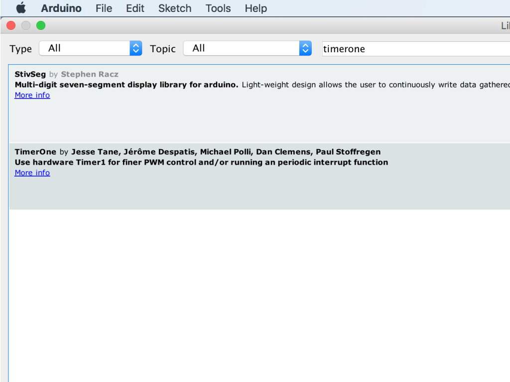
Alternatively, on the Arduino IDE, navigate to Tools > Manage Libraries
Type 'timerone' into the search field.
Click the Install button for 'TimerOne by Jesse Tane ...'
#include <TimerOne.h>

// This example uses the timer interrupt to blink an LED
// and also demonstrates how to share a variable between
// the interrupt and the main program.


const int led = LED_BUILTIN;  // the pin with a LED

void setup(void)
{
  pinMode(led, OUTPUT);
  Timer1.initialize(150000);
  Timer1.attachInterrupt(blinkLED); // blinkLED to run every 0.15 seconds
  Serial.begin(9600);
}


// The interrupt will blink the LED, and keep
// track of how many times it has blinked.
int ledState = LOW;
volatile unsigned long blinkCount = 0; // use volatile for shared variables

void blinkLED(void)
{
  if (ledState == LOW) {
    ledState = HIGH;
    blinkCount = blinkCount + 1;  // increase when LED turns on
  } else {
    ledState = LOW;
  }
  digitalWrite(led, ledState);
}


// The main program will print the blink count
// to the Arduino Serial Monitor
void loop(void)
{
  unsigned long blinkCopy;  // holds a copy of the blinkCount

  // to read a variable which the interrupt code writes, we
  // must temporarily disable interrupts, to be sure it will
  // not change while we are reading.  To minimize the time
  // with interrupts off, just quickly make a copy, and then
  // use the copy while allowing the interrupt to keep working.
  noInterrupts();
  blinkCopy = blinkCount;
  interrupts();

  Serial.print("blinkCount = ");
  Serial.println(blinkCopy);
  delay(100);
}
Replace the previous code with the following in the Arduino IDE.
Upload the code to the Little Bird Uno R3.
To adjust the timer interrupt period, change the value in Timer1.initialize();
This value can be anything from 1 microsecond to 8,388,480 microseconds, or about 8.4 seconds.
This value can be anything from 1 microsecond to 8,388,480 microseconds, or about 8.4 seconds.