I²C and Arduino
Learn all about the I²C communication protocol
Written By: Cherie Tan
Difficulty
Medium
Steps
16
The I²C or inter-integrated circuit protocol is commonly used for connecting microcontrollers and numerous peripherals together.
In this guide, learn all about the I²C protocol, when and why to use it, and get started with using the Wire.h library. Two Little Bird Uno R3 boards will be used to demonstrate the I²C protocol where one will act as the master device, and the other as the slave device.
Complete this guide to get familiar with the Wire.h library, and start using it in your sketches.
While it was first used to connect peripherals together in a television set, since then, it can be found used in many devices including thermal sensors, real-time clocks, accelerometers, displays, etc.
I²C (Inter-integrated Circuit) is a communication protocol that was designed to enable access to numerous devices, by using only two wires.
It was created in 1982 by Phillips' semiconductor division (now known as NXP), who saw the need for a simplified and standardised way for data lines travelling between various integrated circuits, to communicate.
In order for two devices to communicate, whether they are computers or microcontrollers, there needs to be a method for communication. Serial communication is one of the most common forms of communication for these devices.
There are a number of choices available in terms of serial communication protocols, so why use I²C?
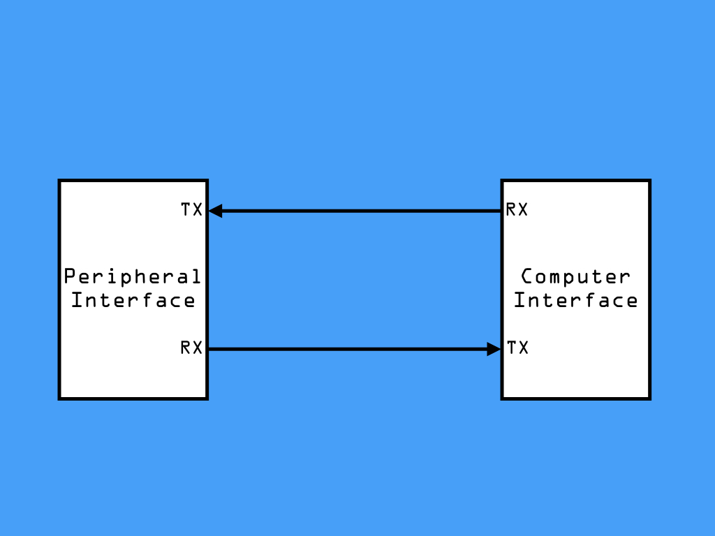
First, let's take a look at what you are likely to be familiar with. If you've programmed your Arduino board to communicate with the serial monitor found in the Arduino IDE on your computer, then you will have already used serial communication. You may have noticed the RX and TX pins to be flashing while something is being printed to the serial monitor. Data is sent on one wire, the transmit wire (TX), and received on another, the receiver wire (RX).
This type of serial communication is asynchronous and based on UART (Universal Asynchronous receiver/Transmitter), not a protocol but a piece of hardware found on the ATmega328 on the Arduino Uno.
There are a number of choices available in terms of serial communication protocols, so why use I²C?
First, let's take a look at what you are likely to be familiar with. If you've programmed your Arduino board to communicate with the serial monitor found in the Arduino IDE on your computer, then you will have already used serial communication. You may have noticed the RX and TX pins to be flashing while something is being printed to the serial monitor. Data is sent on one wire, the transmit wire (TX), and received on another, the receiver wire (RX).
This type of serial communication is asynchronous and based on UART (Universal Asynchronous receiver/Transmitter), not a protocol but a piece of hardware found on the ATmega328 on the Arduino Uno.
Asynchronous communication means that data is transferred without an external clock line. While ideal for reducing the wires and I/O pins involved, the two devices using UART require their own independent clock and will need to agree on the speed (called baud rate) at which to exchange data.
If one device is sending data faster or slower than the other, then this excessive difference in the communication will be misinterpreted. Has the serial monitor shown lots of strange characters? Then the baud rate has probably not been set the same between the two devices.
If one device is sending data faster or slower than the other, then this excessive difference in the communication will be misinterpreted. Has the serial monitor shown lots of strange characters? Then the baud rate has probably not been set the same between the two devices.
Another disadvantage of serial UART communication is that it is intended for one to one device communication. On the other hand, I²C is a synchronous serial communication protocol.
Unlike asynchronous serial communication, synchronous communication involves the use of a common clock line.
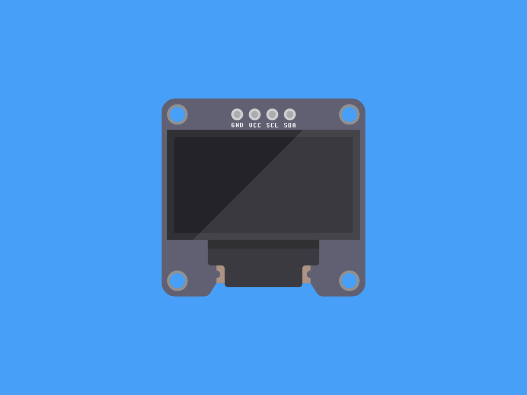
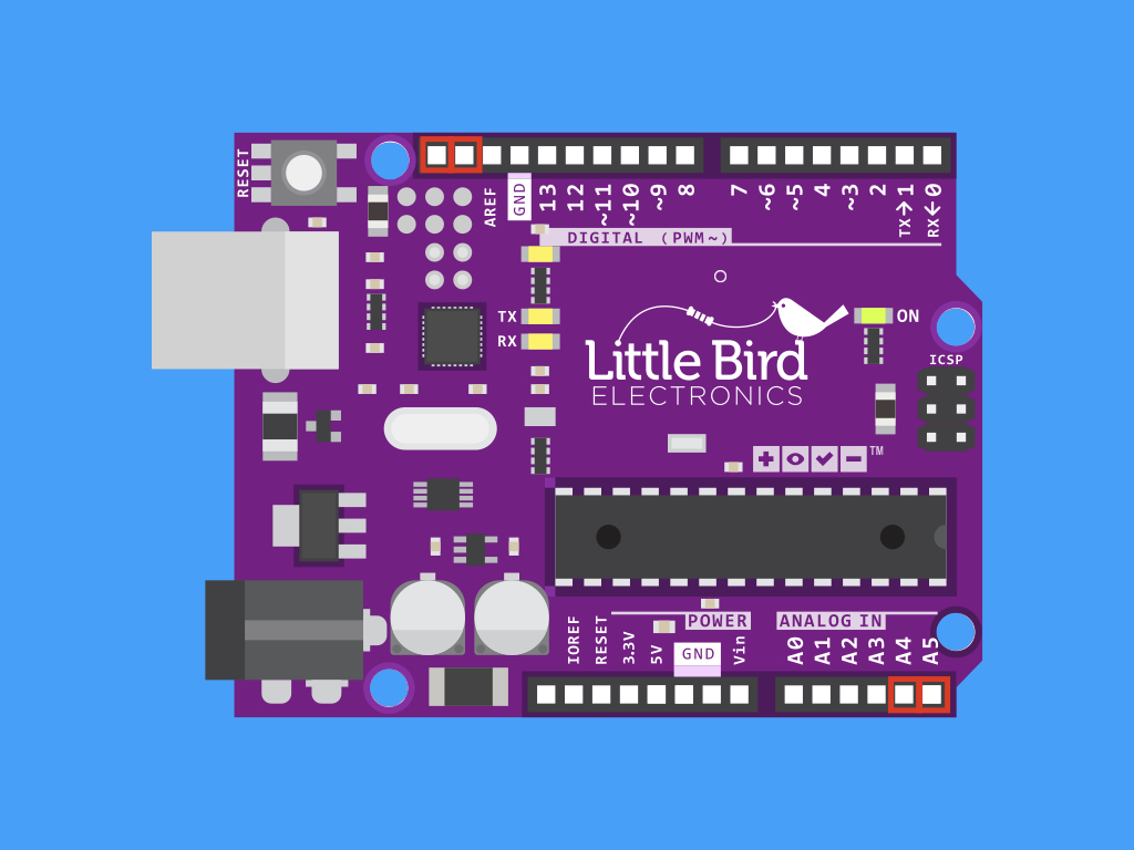
If you take a look at devices that utilise I²C such as an OLED module or real-time clock module, you will notice pins labelled SDA (for Serial Data), and SCL (for Serial Clock). On the Little Bird Uno R3, the SDA (data line) and SCL(clock line) are on the pin headers close to the AREF pin. They are also connected to A4 and A5, respectively.
All such devices if hooked to the I²C network are connected to these two pins.
Both SDA and SCL lines are open drain, which means they require a pull-up resistor. The Arduino board has internal pull-up resistors that are automatically activated on both the SDA and SCL lines when the I²C connection is initialised.
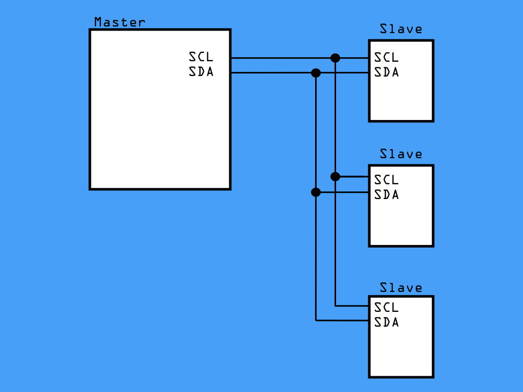
The I²C Protocol utilises a master/slave scheme. All devices connected on the I²C bus are either a 'master' or 'slave'. Generally, the Arduino is the 'master', which drives the clock line (SCL) and so initiates communication.
It can support communication with multiple master devices. However, the master devices aren't able to communicate with each other over the bus, and they would need to wait for their turn on the bus.
Firstly, for the master and slave devices to communicate, a system of registers is used. A register is a small memory location on each device, where data can be stored and retrieved; it can then be read or written to.
For example, a temperature sensor has a register that contains the temperature reading. When the master device asks for information, it asks for the contents of this register. To read or write data, it will need details such as: slave address, the register number, is it a read or write operation, and the length of data.
For example, a temperature sensor has a register that contains the temperature reading. When the master device asks for information, it asks for the contents of this register. To read or write data, it will need details such as: slave address, the register number, is it a read or write operation, and the length of data.
Each slave device has a unique address number, and the master must send this address to the network for the slave to answer.
The standard length for I²C addresses is 7-bit addressing, which yields an address between 0 to 127.
Sometimes, 8-bit addressing is shown in documentation, this is really just displaying the 7-bit address of the slave, followed by the read/write bit on the end of it
The standard length for I²C addresses is 7-bit addressing, which yields an address between 0 to 127.
Sometimes, 8-bit addressing is shown in documentation, this is really just displaying the 7-bit address of the slave, followed by the read/write bit on the end of it
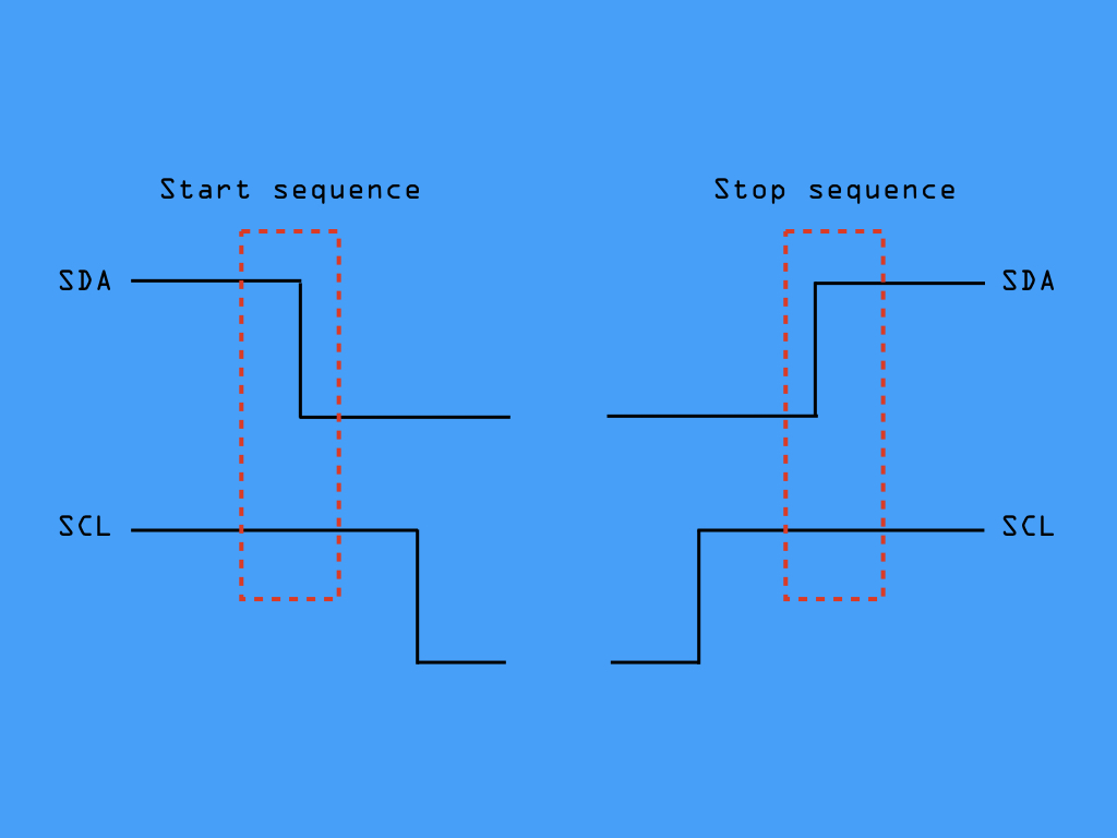
When the master wishes to communicate with the slave device, it first initiates a start sequence on the I²C bus, this happens when SCL line is HIGH, and there must be a HIGH to LOW transition for the SDA line.
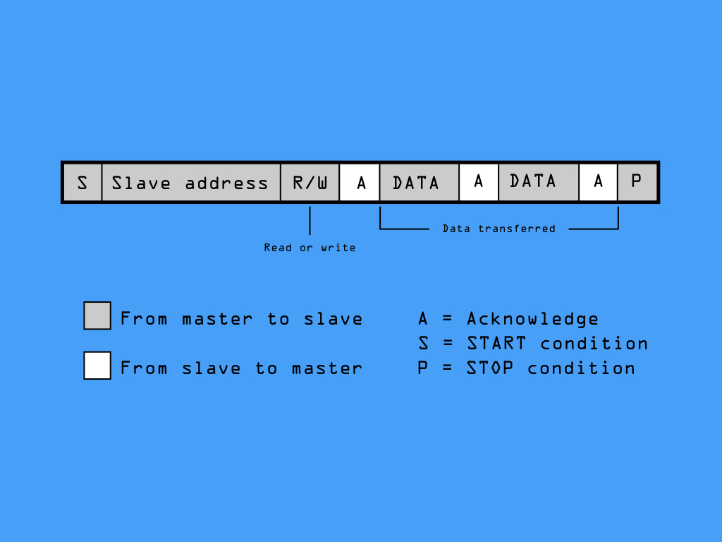
Then, data is transferred in sequences of 8 bits (a byte) -- the first 7-bits are the slave address, and the next bit after that is the data direction bit. If this is 0 then the master writes to the slave device. Otherwise, if the data direction bit is 1, the master will read from the slave device. After the slave address and data direction bit is transmitted, the master device continues reading or writing to the slave device.
To stop communication, it uses a stop sequence -- for this, there must be a LOW to HIGH transition for SDA line, and again, the SCL line needs to be HIGH.
#include <Wire.h>The Arduino's Wire library hides all this low-level functionality and enables the use of simple commands to initialise and communicate with slave devices.
To set up the Wire library, it must first be initialised. The easiest way to do so is to type: #include <Wire.h> up the top of your sketch.
#include <Wire.h>

void setup()
{
  Wire.begin(); // configure the Arduino as an I2C master
}
Next, we will need to declare the Arduino as an I²C device, over in setup, call Wire.begin().
If the Arduino is used as a slave, you must specify an address like so:
Wire.begin(address); // configures the Arduino as an I2C slave
Wire.begin(address); // configures the Arduino as an I2C slave
#include <Wire.h>

void setup()
{
  Wire.begin(); // configure the Arduino as an I2C master
}

void loop()
{
  Wire.beginTransmission(44); // transmit to device #44 (0x2c)
  // device address is specified in datasheet
}
To start sending data, first use a beginTransmission function. It takes one parameter, which is the destination address of the I²C device on the bus that you want to send data to.
#include <Wire.h>

byte val = 0;

void setup()
{
  Wire.begin(); // configure the Arduino as an I2C master
}

void loop()
{
  Wire.beginTransmission(44); // transmit to device #44 (0x2c)
  // device address is specified in datasheet
  Wire.write(val);             // sends value byte
}
Next, to send information to the slave device, this can be done by using Wire.write().
#include <Wire.h>

byte val = 0;

void setup()
{
  Wire.begin(); // configure the Arduino as an I2C master
}

void loop()
{
  Wire.beginTransmission(44); // transmit to device #44 (0x2c)
                              // device address is specified in datasheet
  Wire.write(val);             // sends value byte
  Wire.endTransmission();     // stop transmitting
}
To specify the end of a message, and send it, this can be done by using Wire.endTransmission().
The Wire.endTransmission function also takes an optional parameter, stop.
stop : boolean. true will send a stop message, releasing the bus after transmission. false will send a restart, keeping the connection active.
By using Wire.endTransmission(stop), this frees the I²C bus. Without using 'stop', the master can continue to issue orders. By default, the value is true.
stop : boolean. true will send a stop message, releasing the bus after transmission. false will send a restart, keeping the connection active.
By using Wire.endTransmission(stop), this frees the I²C bus. Without using 'stop', the master can continue to issue orders. By default, the value is true.
#include <Wire.h>

void setup()
{
  Wire.begin();        // join i2c bus (address optional for master)
  Serial.begin(9600);  // start serial for output
}

void loop()
{
  Wire.requestFrom(4, 6);    // request 6 bytes from slave device #4

  while (Wire.available())   // Repeat as long as there is data waiting
  {
    char c = Wire.read();    // receive a byte as character
    Serial.print(c);         // print the byte
  }

  delay(500);
}
For a master device to receive data from a slave device, it must first make a request, and this can be done by using Wire.requestFrom(address,quantity);
The first argument specifies the address of the slave device it wants to receive data from. The second argument requires the number of bytes that the slave will send.
There is an optional parameter, ‘stop’ which specifies if the bus should be released. It can be used as so:
Wire.requestFrom(address, quantity, stop);
The slave device is allowed to return less than the stated amount, and the master device will just read all the available information.
After creating a request and sending it to the I2C bus, the master device then waits for a message back. The slave transmits a message back, and this information can be stored in a variable like so:
data = Wire.read();
data = Wire.read();
Keep in mind that the Wire.read() function reads a single byte of information. For multiple bytes of information, this function must be called for each byte.
To see if there is available data, the Wire.available() function is used. If there is information, it returns the amount of bytes remaining. Use it with a while loop and with Wire.read as such.
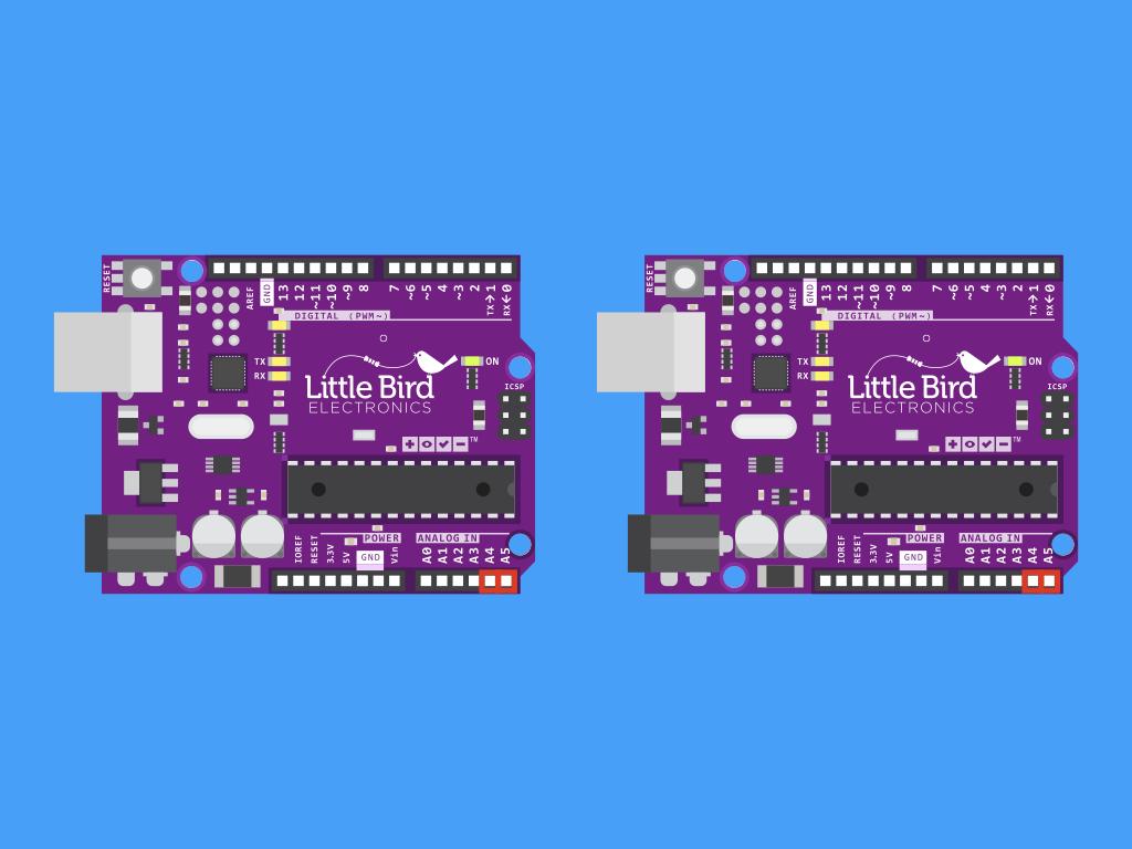
In the next part of this guide, we'll demonstrate how you can get two Arduino boards communicating with each other through the I2C protocol. In this case, one Little Bird Uno R3 will act as the master and the other, the slave device.
The connections are simple as the Little Bird Uno R3 has internal pull-up resistors already in place. So, the SDA pins on both Arduino boards will be connected together. Then the SCL pins on both boards are connected together. Finally, they will share one GND line.
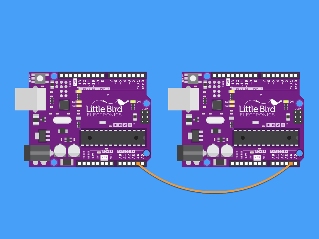
Insert a jumper wire into A4 of one Little Bird Uno R3
Connect the other end of this jumper wire to A4 on the second Little Bird Uno R3
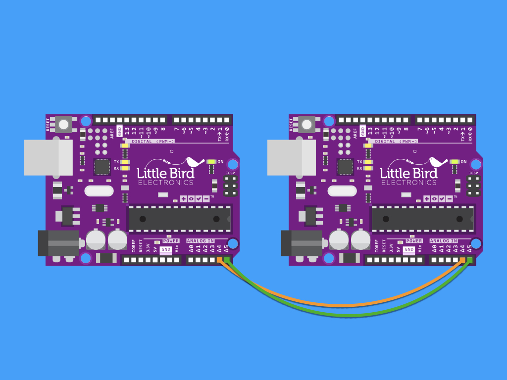
Next, insert a jumper wire into A5 of the first Little Bird Uno R3
Insert the other end of this jumper wire to A5 of the second Little Bird Uno R3
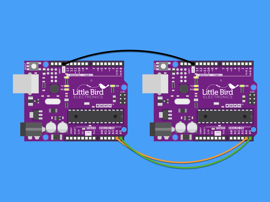
Finally, insert a black jumper wire to GND on one Little Bird Uno R3.
Complete the connection by inserting the other end of this jumper wire to GND on the second Little Bird Uno R3.
#include <Wire.h>

int LED = 13;
int x = 0;

void setup() {
  // Define the LED pin as Output
  pinMode (LED, OUTPUT);
  // Start the I2C Bus as Slave on address 8
  Wire.begin(2);
  // Register I2C callbacks
  Wire.onReceive(receiveEvent);
}

void receiveEvent(int byteCount) {
  while (Wire.available())
  {
    x = Wire.read();
    //If value received is 1, turn LED off
    if (x == 1) {
      digitalWrite(LED, LOW);
    }
    //If value received is not 1, turn LED on
    else {
      digitalWrite(LED, HIGH);
    }
  }
}

void loop() {
  //do nothing
  delay(100);
}
Upload this code to the Little Bird Uno R3 that will act as the slave device.
In setup, the Wire library is initiated, and the board joins the I²C bus as a slave device with the address #8.
Next, an I²C callback is set up with Wire.onReceive which will call the receiveEvent function whenever it receives a transmission from a master.
If the value it receives is 1, the built-in LED on the slave device will turn off. Otherwise, the LED will stay on!
#include <Wire.h>

int x = 0;

void setup() {
  // Start the I2C Bus as Master
  Wire.begin();
}
void loop() {
  Wire.beginTransmission(8); // transmit to device #8
  Wire.write(x);              // sends x
  Wire.endTransmission();    // stop transmitting
  x++; // Increment x
  if (x > 4) {
    x = 0; // reset x once it is bigger than 4
  }
  delay(500);
}
Upload this code to the Little Bird Uno R3 that will act as the master device.
We have created a variable x that will act as a counter. It will increment within the loop function, and once the x value is '5', the counter will reset.