How to Use an RGB LED with Arduino
Learn to use a multi colour LED
Written By: Cherie Tan

Difficulty
Easy
Steps
11
While RGB LEDs look like conventional LEDs, they are three-in-one, comprising of a red, green and blue LED.
In this guide, we will learn how to control the brightness of each LED and so, change the colour of an RGB LED. We will be using a Little Bird Uno R3 development board, and a Multicolor RGB LED with White Diffused Lens, a mini breadboard and some jumper wires.
After completing this guide, you will be one step ahead with creating your own devices that require illumination or indication, such as an LED cube or an animated pixel art box!


Insert a 220 Ohm Resistor in line with the Red Pin (pin on the flat side) of the RGB LED.
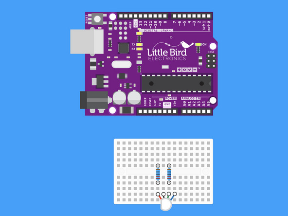
Insert a 220 Ohm Resistor in line with the Green Pin of the RGB LED.

Insert a 220 Ohm Resistor in line with the Blue Pin of the RGB LED
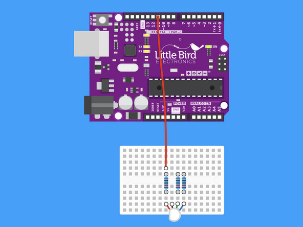
Run a jumper from Digital Pin 11 to the 220 Ohm Resistor on the Red Pin.
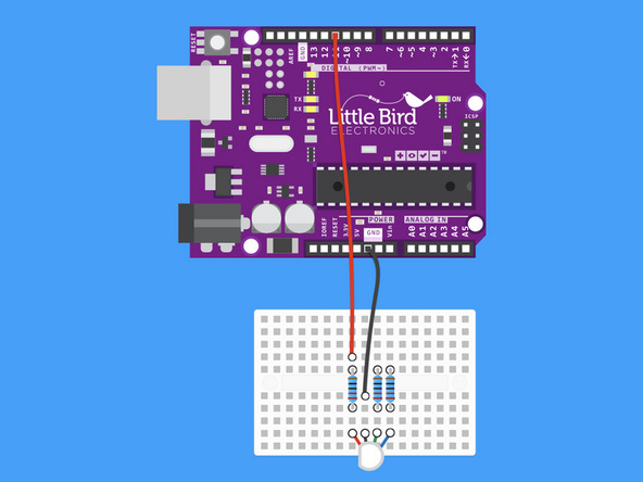
Run a jumper from Ground to the Ground / Cathode Pin of the RGB LED.

Run a jumper from Digital Pin 10 to the 220 Ohm Resistor on the Green Pin.
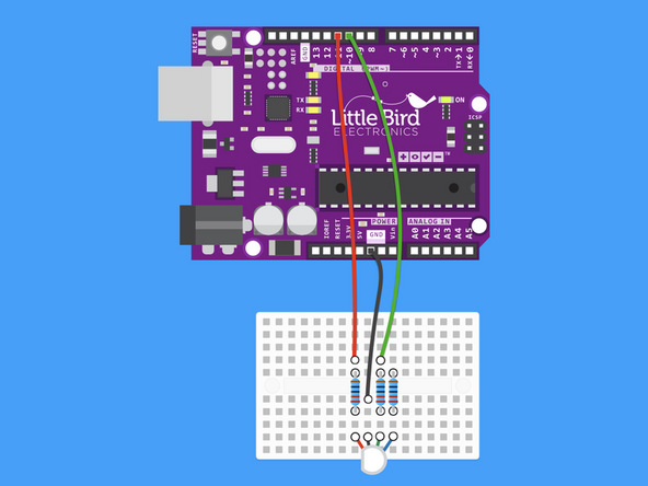
Run a jumper from Digital Pin 10 to the 220 Ohm Resistor on the Green Pin.

Run a jumper from Digital Pin 9 to the 220 Ohm Resistor on the Blue Pin.
int redPin = 11;
int greenPin = 10;
int bluePin = 9;

void setup() {

  //  Set the RGB LED pins as OUTPUTs
  pinMode(redPin, OUTPUT);
  pinMode(greenPin, OUTPUT);
  pinMode(bluePin, OUTPUT);
}

void loop() {
  setColor(255, 0, 0); //  Red
  delay(1000);
  setColor(0, 255, 0); // Green
  delay(1000);
  setColor(0, 0, 255); // Blue
  delay(1000);
  setColor(255, 255, 0); // Yellow
  delay(1000);
  setColor(80, 0, 80); // Magenta
  delay(1000);
  setColor(0, 255, 255); // Cyan
  delay(1000);
}

// This is a function. You can think of a function
// as a predefined snipped of code that you can call upon
// within your program.

// A function in Arduino starts with the "return type".
// The "return type" is the type of data the function
// will return.

// In our example the function doesn't return anything
// When we have a function that doesn't return anything,
// we put "void" as teh return type

void setColor(int red, int green, int blue) {
  analogWrite(redPin, red);
  analogWrite(greenPin, green);
  analogWrite(bluePin, blue);
}
Grab this code and upload it in the Arduino IDE.
Your RGB LED should start to cycle through the colours. There is a 1 second delay on each colour change.