Heart Rate Sensor with Arduino
Get ECG signals with the AD8232 Heart Rate Sensor and Arduino
Written By: Cherie Tan
Difficulty
Medium
Steps
16
Electricity is everywhere, even in the human body! Our tiny cells are specialised to conduct electrical current, and that's what makes the heart go. Often, to diagnose heart conditions, Electrocardiogram is used. An electrocardiogram or ECG, is nothing more than a recording of the heart's electrical activity.
The AD8232 is a chip used to measure the electrical activity of the heart. In this guide, we'll show you how to get an ECG signal reading from the AD8232 Heart Rate Sensor with our 100% Arduino-compatible board, the Little Bird Uno R3.
The AD8232 is a chip used to measure the electrical activity of the heart. In this guide, we'll show you how to get an ECG signal reading from the AD8232 Heart Rate Sensor with our 100% Arduino-compatible board, the Little Bird Uno R3.
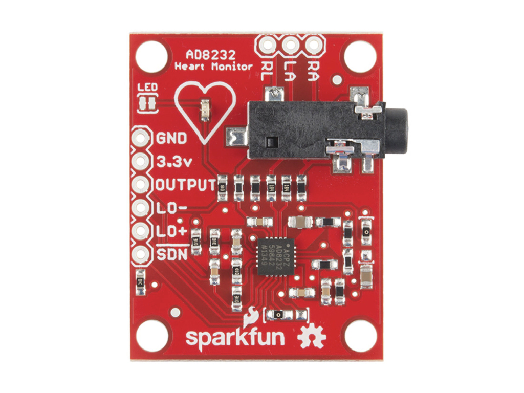
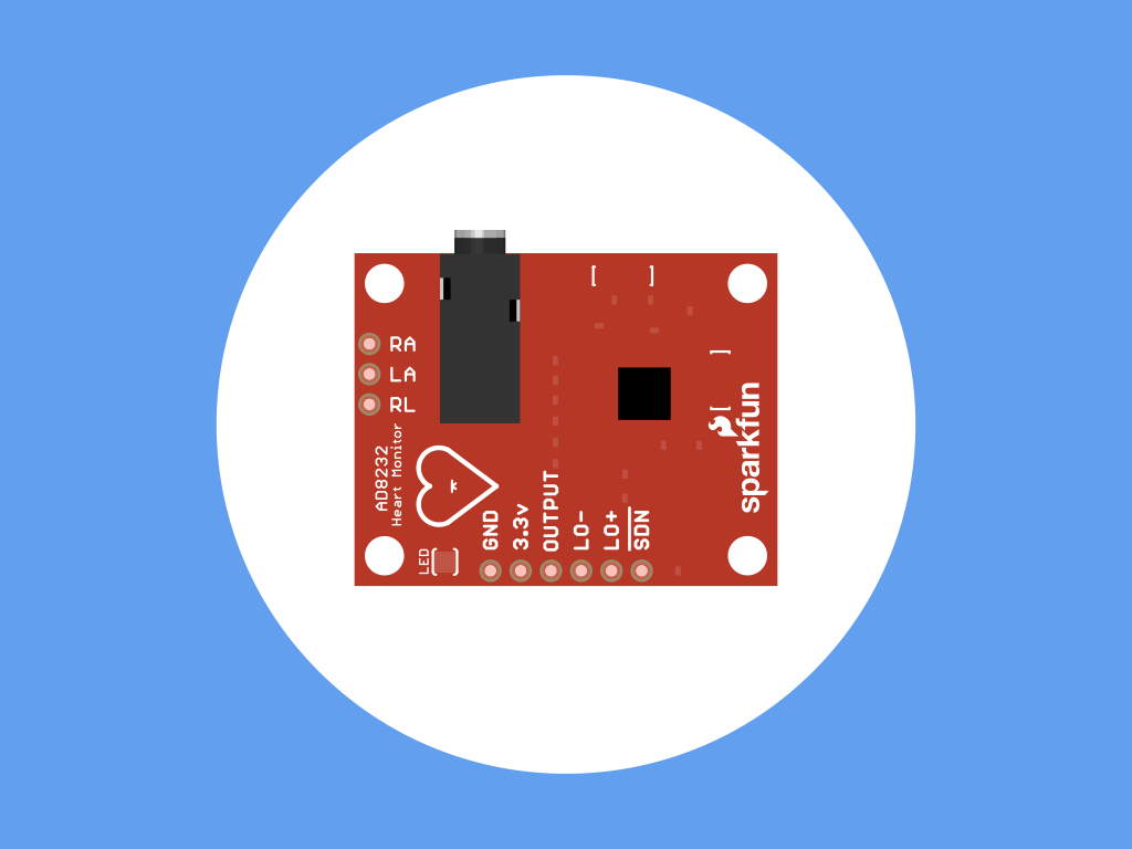
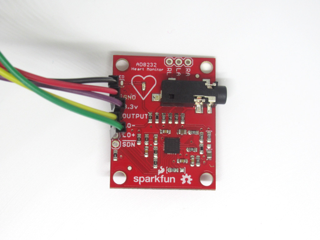
This heart rate sensor module comes with the integrated circuit AD8232, a single lead or three electrode configuration, and a 3-pole adjustable low-pass filter with adjustable gain.
There are nine connections from the module that you can solder pins, wires, or other connectors to. The essential pins are:
GND : Connect this to the GND pin on the Uno R3
3.3V : Connect this to the 3.3V pin on the Uno R3
OUTPUT : This pin is responsible for the Analog Output Signal. Connect this to an analog pin on the Uno R3
LO- : Leads-off Detect -
Connect this to a digital pin on the Uno R3
LO+ : Leads-off Detect +
Connect this to another digital pin on the Uno R3
SDN : This is the 'shutdown' pin, and will be left unconnected in the guide. However, connecting this pin to ground or "LOW" on a digital pin will power down the chip, making it useful for low-power applications.
Up the top right-hand corner, there are three other pins, RA (Right Arm), LA (Left Arm), and RL (Right Leg). While we won't be using these in the guide, you can use these pins with your own custom sensors.
The LED indicator light is not a PWR LED - it does not reflect whether or not the module is powered. Instead, this LED indicator will pulsate to the rhythm of a heart beat.
In this guide, we'll show you how to connect it up to an Uno R3 - Little Bird, then measure and monitor the electrical activity of your heart first in the Arduino IDE.
To understand how ECG works, we'll need to take a closer look at the heart.
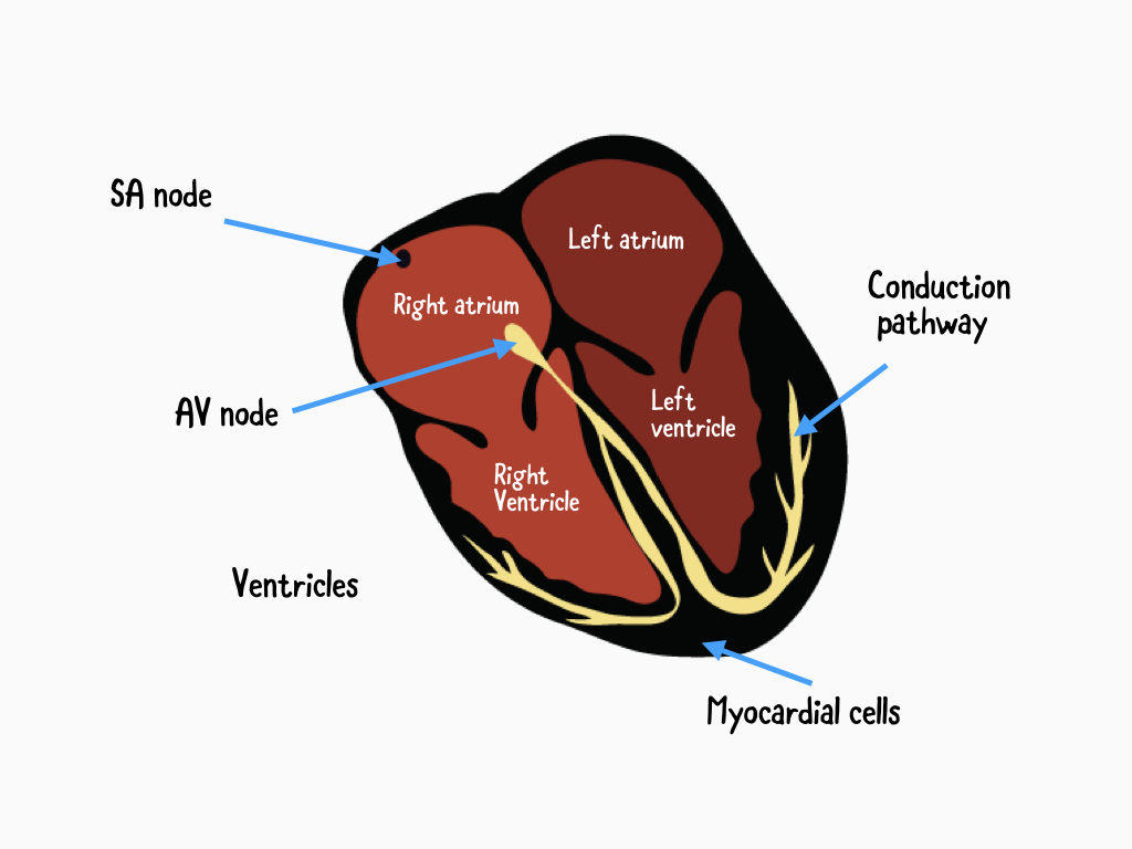
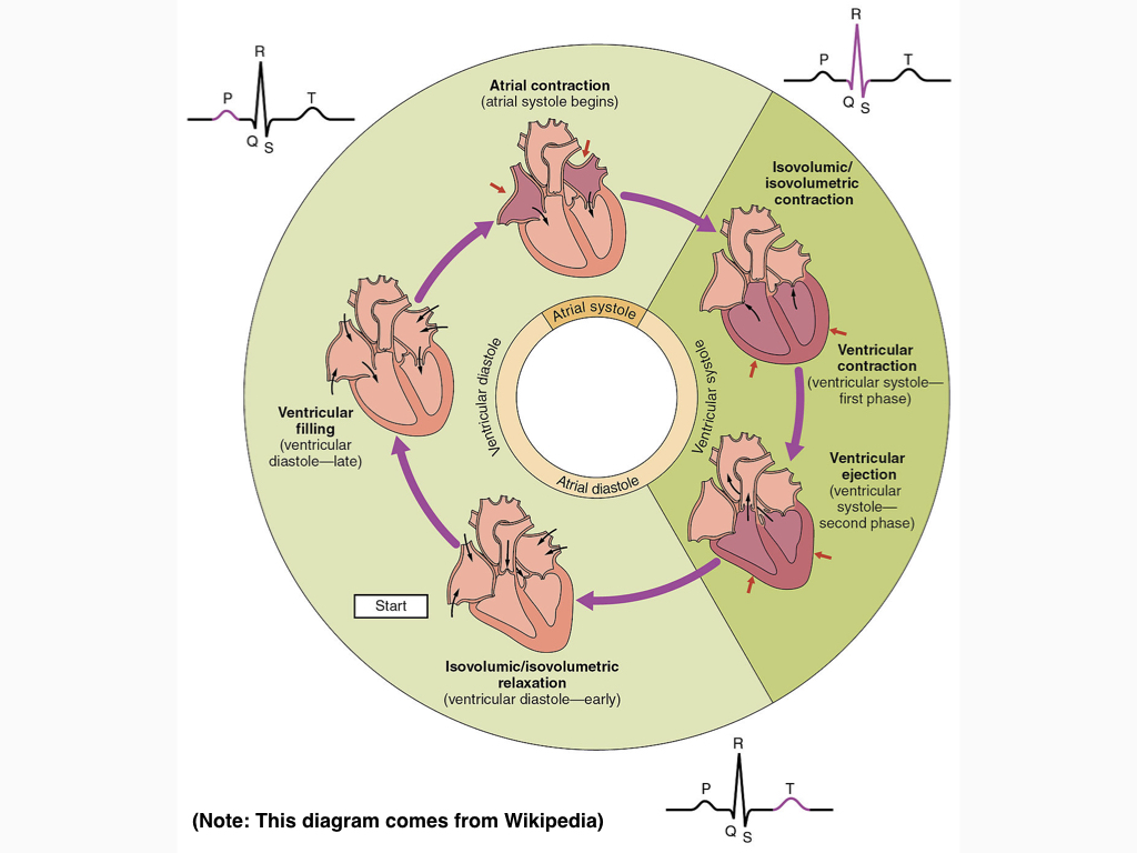
The heart can be thought of as a two-stage pump, divided into two sides. Each side has an atrium at the top, and a ventricle at the bottom. Most of the heart is comprised of myocardial cells, which is basically the contractile machinery of the heart.
Due to electrical impulses generated by a group of pacemaker cells called the sinus node (SA node), our heart muscles are activated and this results in its blood-pumping action.
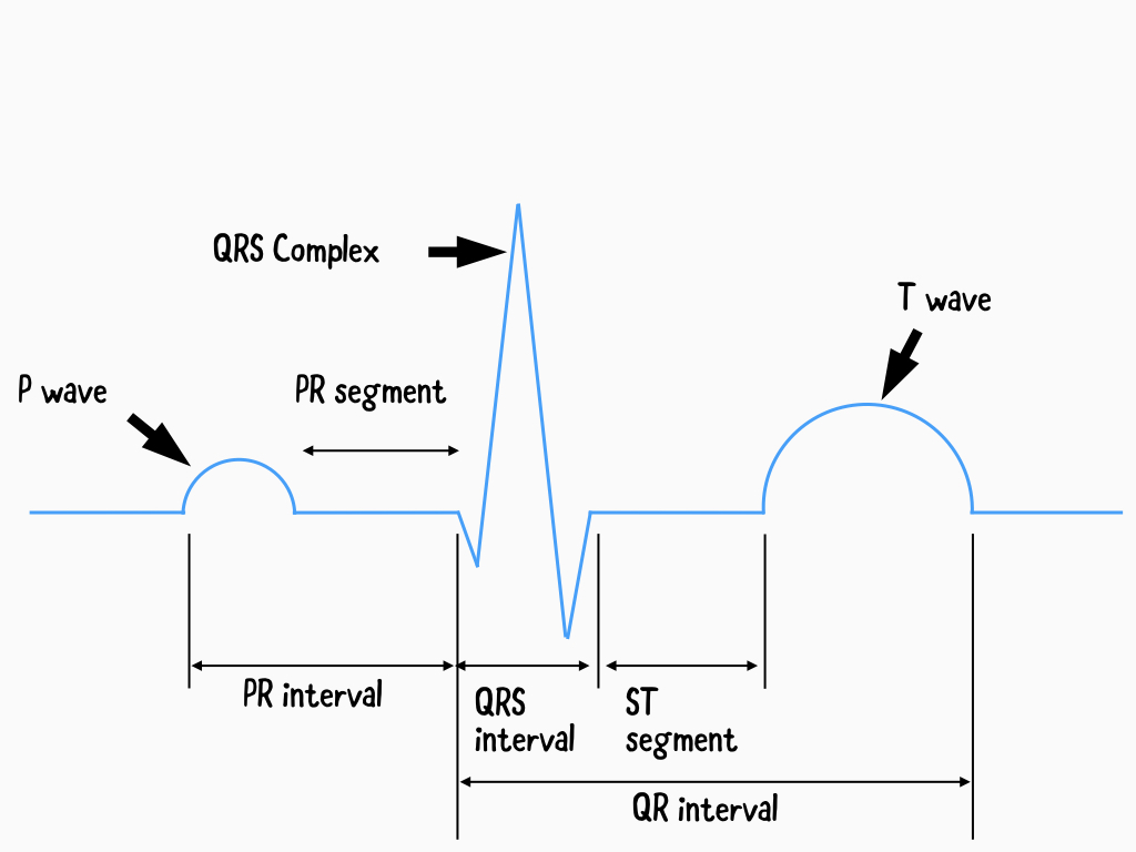
The waves that appear in an ECG waveform reflects the electrical activity from heart contractions, and its pattern is made of several different parts.
The heart can be thought of as a two-stage pump, divided into two sides. Each side has an atrium at the top, and a ventricle at the bottom. Most of the heart is comprised of myocardial cells, which is basically the contractile machinery of the heart.
Due to electrical impulses generated by a group of pacemaker cells called the sinus node (SA node), our heart muscles are activated and this results in its blood-pumping action.
The waves that appear in an ECG waveform reflects the electrical activity from heart contractions, and its pattern is made of several different parts.
During a normal heartbeat, the electrical activity starts in the SA node. When atrial depolarisation occurs, this causes the two upper chambers of the heart to contract (atrial contraction), which produces a small wave called the P wave.
Next, the QRS complex represents the electrical activity running first from the atrioventricular node (AV node), then to the inter-ventricular septum, and finally to the two large lower chambers (ventricular contraction). This produces the big up and down in the middle, QRS complex.
Finally, the T wave is the recovery period as the electrical impulse reverses and travels back over the ventricles. The T-wave occurs just before ventricle relaxation, and can be thought of as the electrical reset of the heart in preparation of the next cardiac cycle
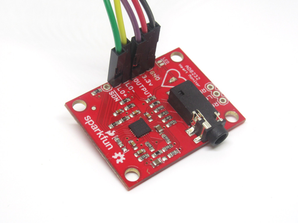
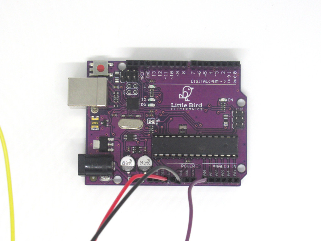
To use the AD8232 Heart Rate Sensor with the Arduino, we'll first need to solder header pins or jumper wires to it. In this guide, we've soldered M-M jumper wires directly onto the AD8232 Heart Rate Sensor.
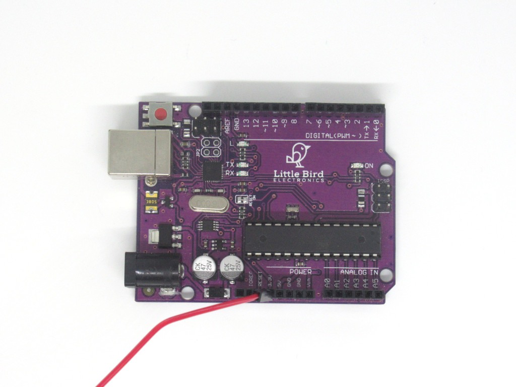
Insert the red jumper wire attached to 3.3V on the AD8232 into 3.3V on the Uno R3.

Insert the jumper wire connected to OUTPUT on the AD8232, to A0 on the Uno R3.
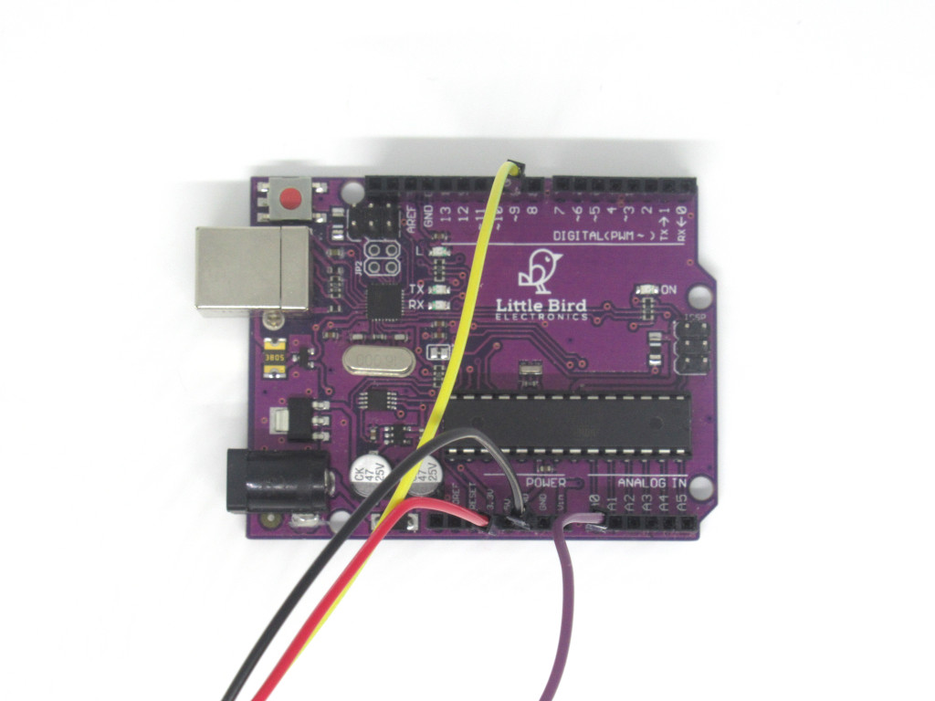
Insert the jumper wire currently connected to LO+ on the AD8232, to digital pin 9 on the Uno R3.
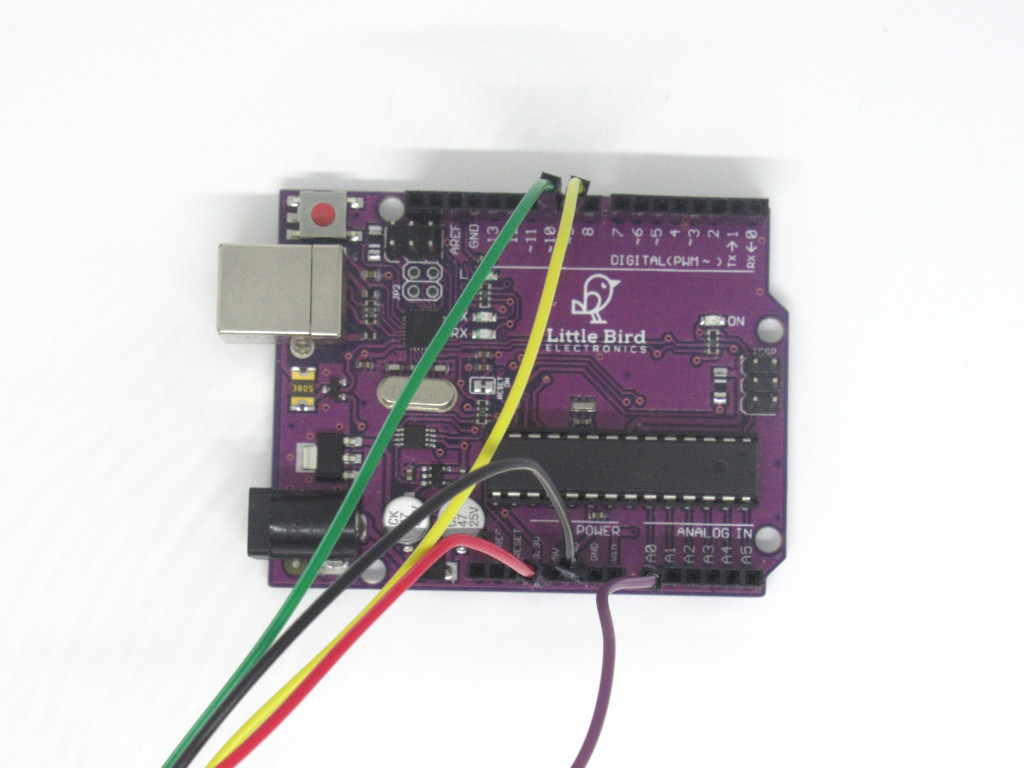
Insert the jumper wire connected to LO- on AD8232 to digital pin 10 on the Uno R3.
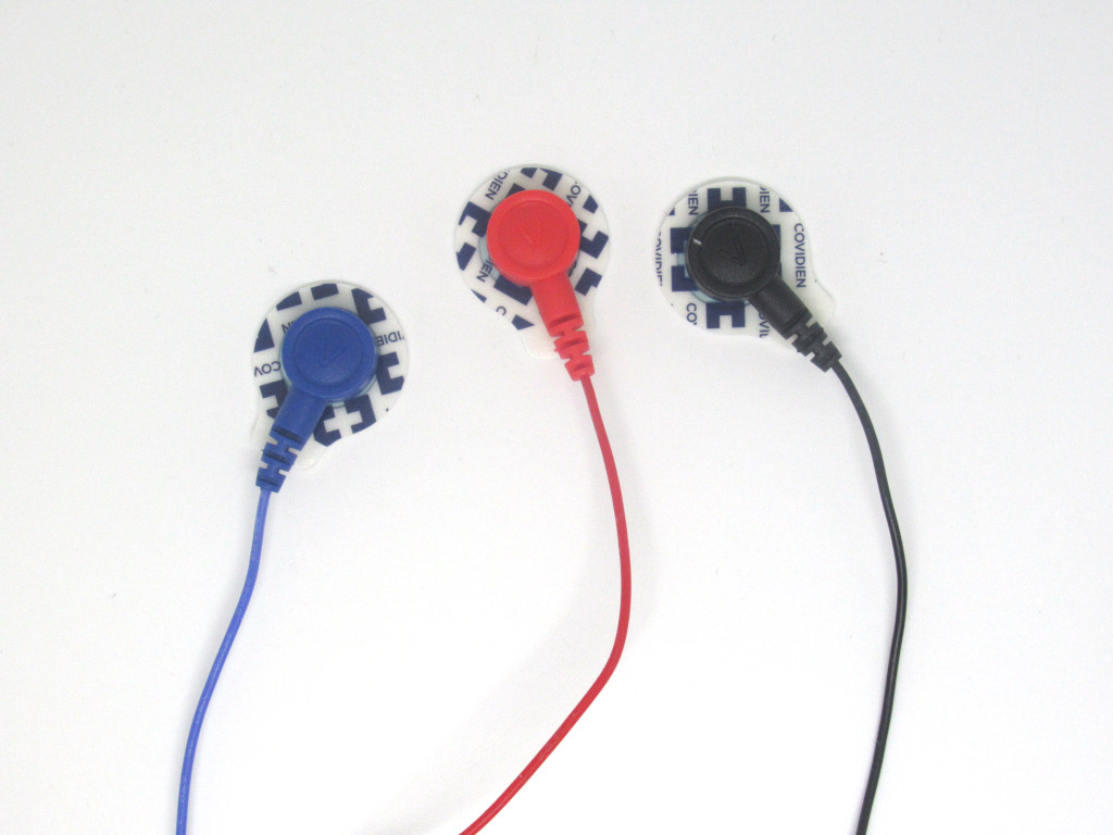
Carefully attach a biomedical sensor pad to each snap-style receptacle.
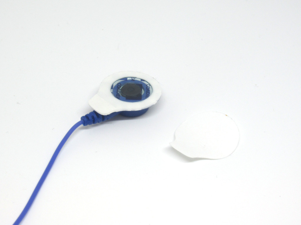
Peel off the back from the electrode pad.
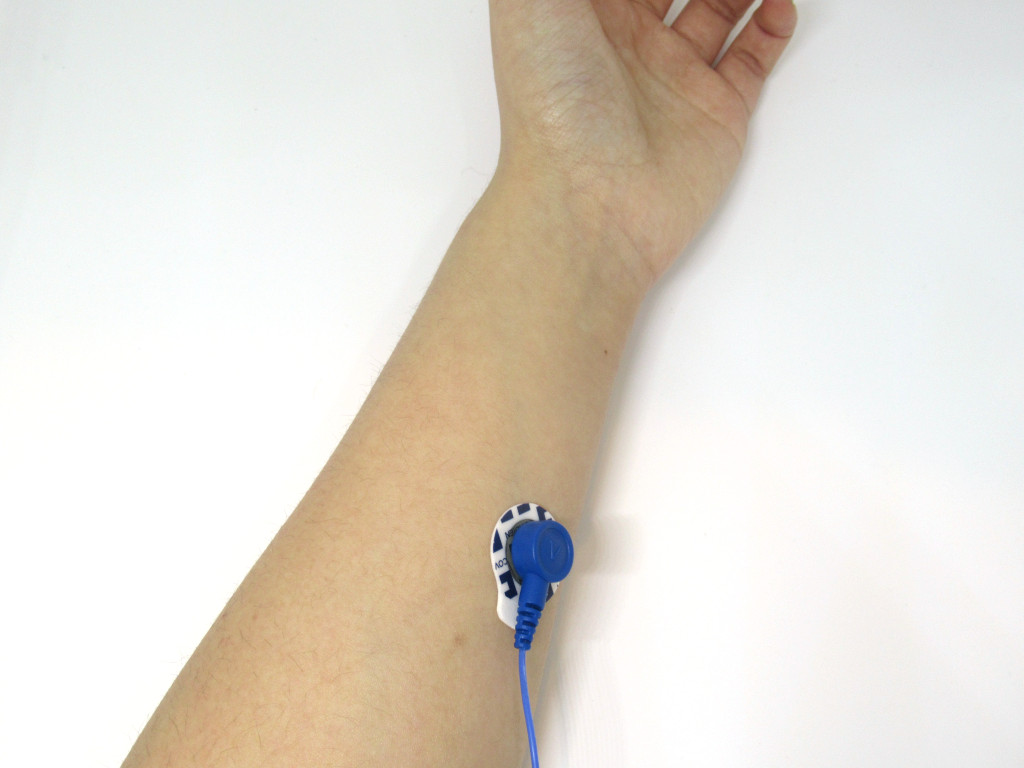
Place the electrode pad (blue) onto the left arm.
Place the electrode on soft tissue as electric pulse can hardly travel through the skeleton due to its poor conductivity.
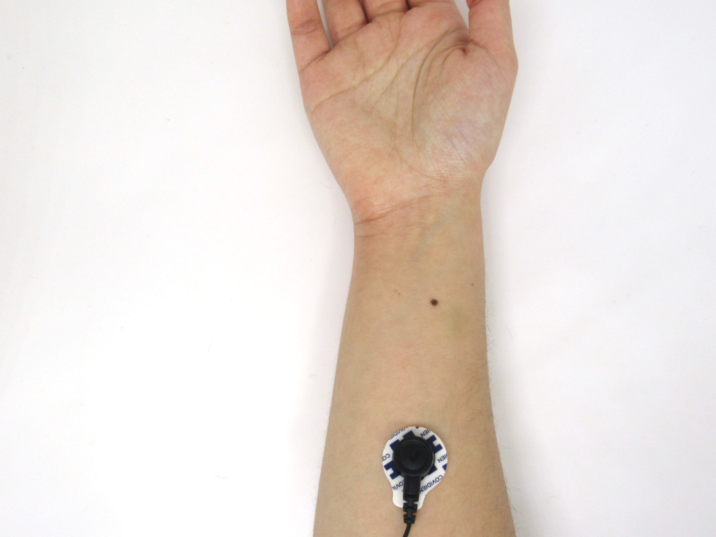
Attach the electrode (black) to the right arm.
Likewise, peel off the back from the next electrode pad.
Again, peel off the back from the next electrode pad.
Attach the electrode (red) to the right leg.
void setup() {
  // initialize the serial communication:
  Serial.begin(9600);
  pinMode(9, INPUT); // Setup for leads off detection LO +
  pinMode(10, INPUT); // Setup for leads off detection LO -

}

void loop() {

  if((digitalRead(9) == 1)||(digitalRead(10) == 1)){
    Serial.println('!');
  }
  else{
    // send the value of analog input 0:
      Serial.println(analogRead(A0));
  }
  //Wait for a bit to keep serial data from saturating
  delay(1);
}
Copy and paste this code into the Arduino IDE.
An accurate measurement of an ECG signal depends on a low-impedance conductive path from the body to the monitoring device. If there is a disruption between them, the results may not be very accurate. One way to tackle this problem is through a technique called lead-off detection, which verifies that electrodes are properly connected. This is what the LO- and LO+ pins are used for.
Data coming from these pins is used to detect for "lead-off" signal. This happens when an electrode is making poor electrical contact. Since this is not valid data for our purposes, it can be discarded. Therefore, we've programmed it so that it will print out, "!" to mark it as invalid data. On the other hand, anything coming from Analog In Pin A0 is regarded as valid data.
Data coming from these pins is used to detect for "lead-off" signal. This happens when an electrode is making poor electrical contact. Since this is not valid data for our purposes, it can be discarded. Therefore, we've programmed it so that it will print out, "!" to mark it as invalid data. On the other hand, anything coming from Analog In Pin A0 is regarded as valid data.
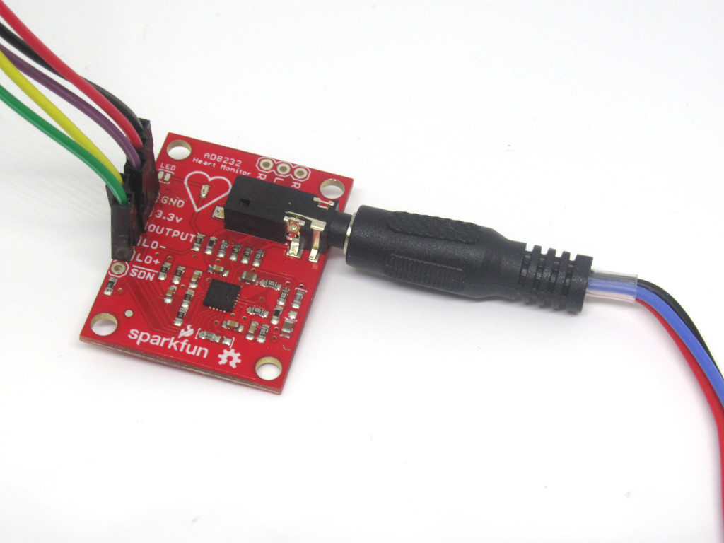
Next, connect the 3.5mm audio jack connector on one end of the sensor cable to the AD9232 Heart Rate Sensor.
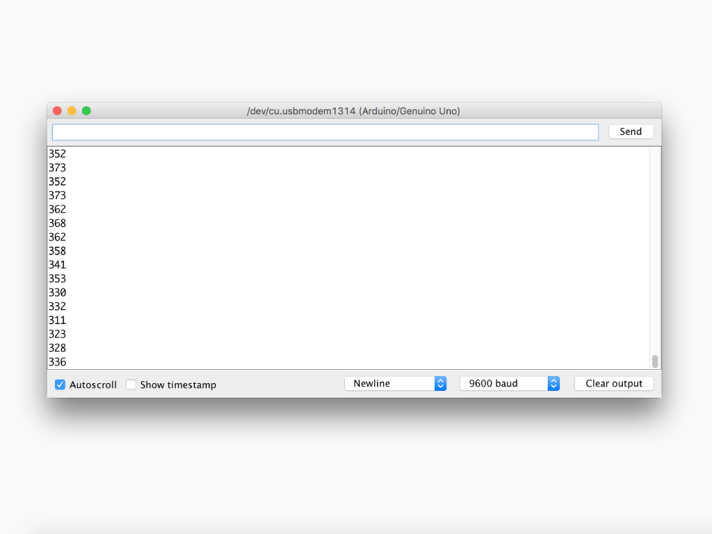
To verify that it is all working, open up the Serial Monitor by clicking on Tools > Serial Monitor in the Arduino IDE.
Make sure the baud rate is set to 9600 baud. This can be seen on the bottom right-hand corner of the Serial Monitor.
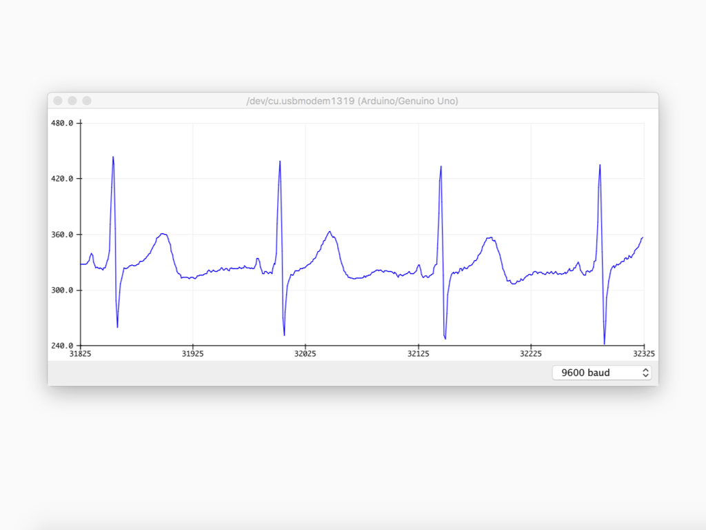
To view the ECG signal, open up the Serial Plotter by going to Tools > Serial Plotter
You should see a waveform similar to the picture as shown on the left.
Make sure the baud rate is set to 9600 baud. This can be set at the bottom right hand corner.
Hold still as regular muscle movement will also generate an electric pulse, and it is ideal to get rid of them.
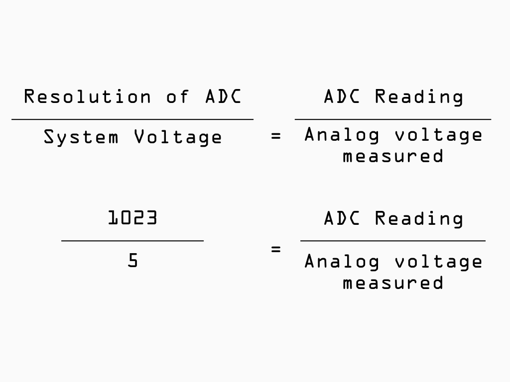
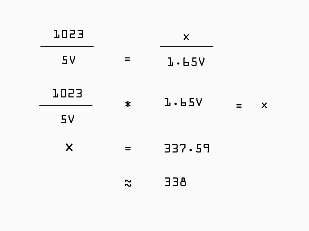
You might notice that the mid-point value of the waveform is around ~338. This is because the the reference voltage for analog input by default on a 5V Arduino board is 5 volts. So its 10-bit ADC would decode a level of 2.5V on an analogue input as ~511. This is fine if the device connected to it is also outputting a signal between 0 and 5V. However, if the device connected to it (in this case, the AD8232 Heart Rate Sensor) is running on 3.3V, then it will only output a maximum of 3.3V. As a result, its midpoint would be 1.65V, which the 5V Arduino's ADC would decode as ~338.
While it is possible to get an ECG waveform, if you would like to go further i.e. calculate BPM with the sensor, it is advised that you pick up a 3.3V Arduino board instead for simplicity.
While it is possible to get an ECG waveform, if you would like to go further i.e. calculate BPM with the sensor, it is advised that you pick up a 3.3V Arduino board instead for simplicity.