Getting Started with the Owl Robot
Assemble all parts of the owl robot from its kit, and then learn to program it with its Arduino microcontroller.
Written By: Cherie Tan
Difficulty
Easy
Steps
20
The Owl Bot is a beginner-friendly, low-cost robotic kit for the Arduino. It's simple to set up, there's no need for dozens of jumper wires, soldering, or a breadboard. In this guide, learn to assemble the Owl Bot and then get started with programming it. Complete this guide to quickly get started with the Owl Bot.
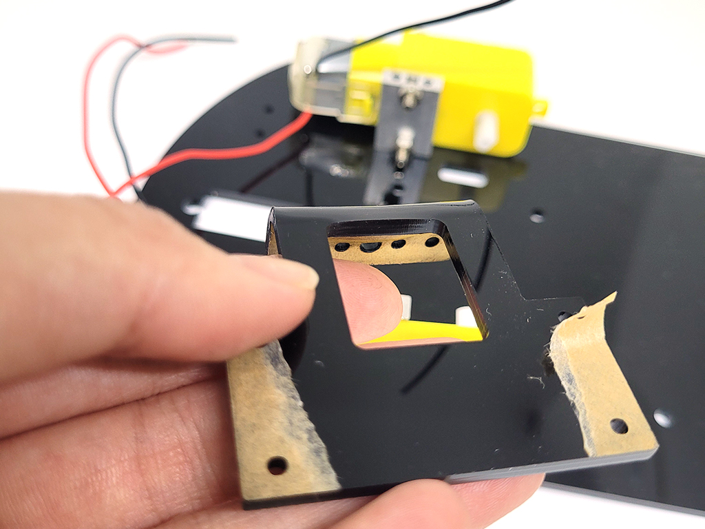
First insert the four long screws for the motors as shown. Insert the nuts to the screws to secure it in place.


Peel the sticker off the other acrylic pieces
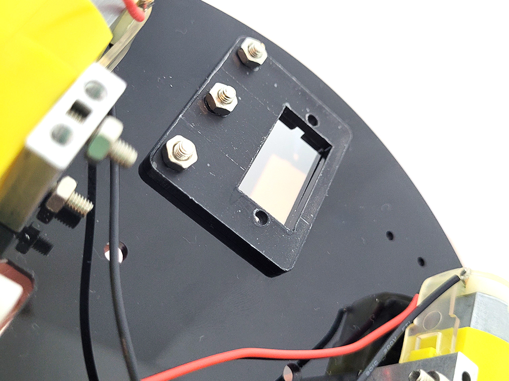
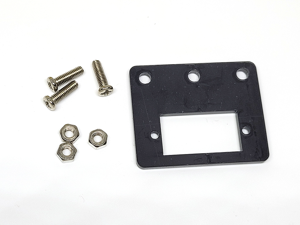
Attach the smaller flat acrylic plate to the chassis with three screws and nuts as shown. The nuts should be attached on the underside.
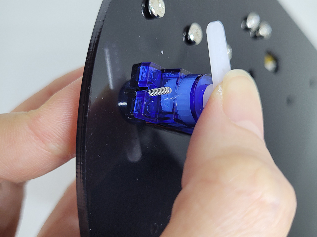
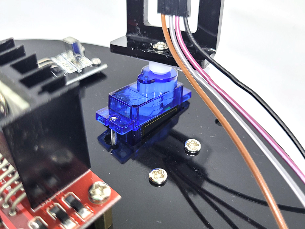
Insert the screws as shown to start securing servo to the acrylic chassis.


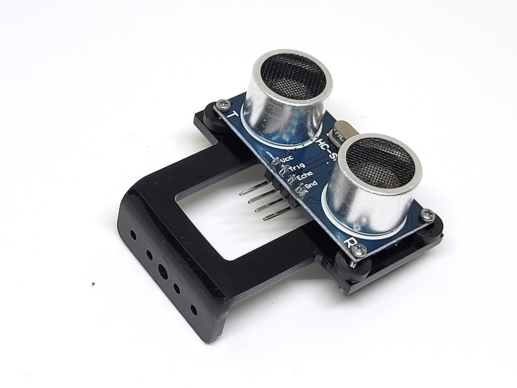
Attach the ultrasonic distance sensor to the bracket as shown, secured with the nuts on the back view.
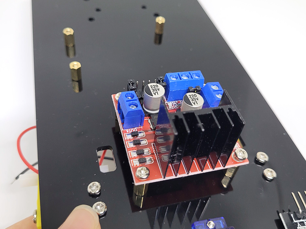
Attach the motor controller to the chassis as shown. The standoffs should be between it and the chassis, secured with screws on bottom side as well a screws on top side.
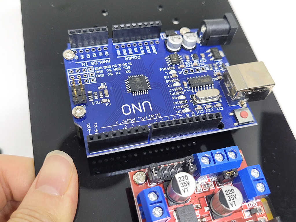
Likewise, first secure three standoffs to the chassis, with the screws coming in from the bottom. Then secure the Arduino with the standoffs with three more screws from the top side.

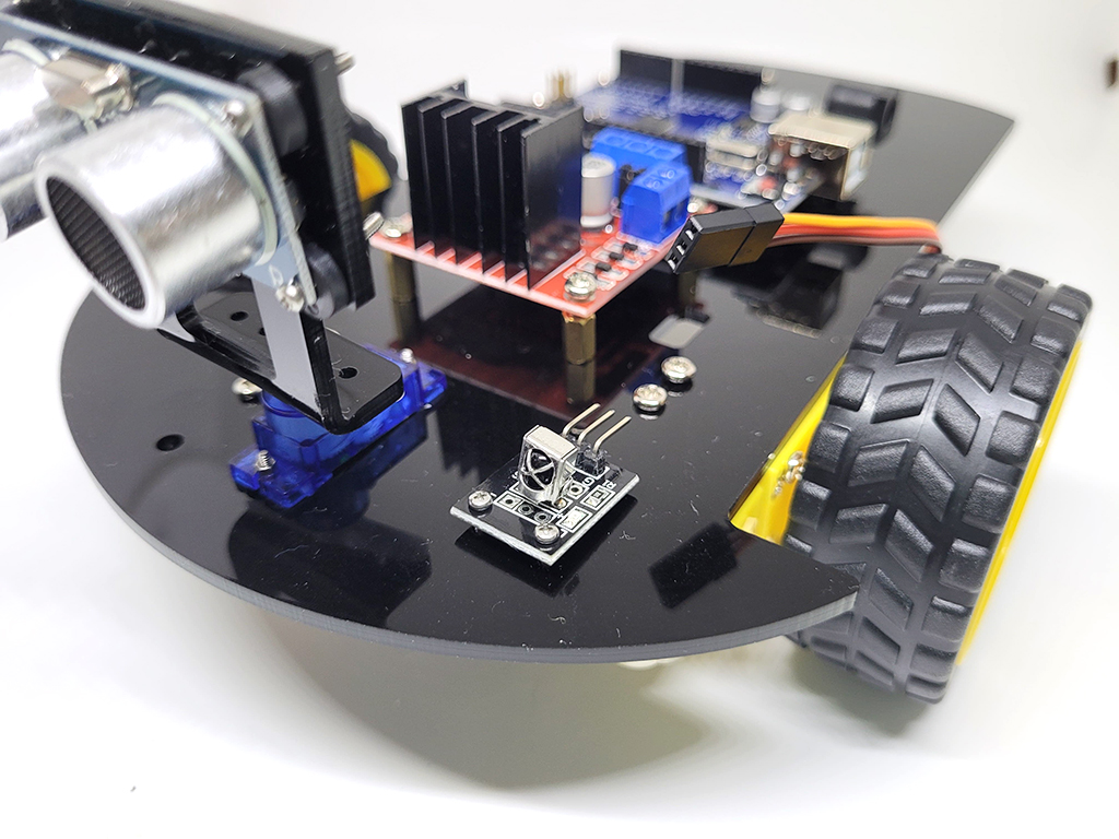
Now attach both wheels to the two motors at the front of the chassis Note: While it is not attached in this build, you may wish to connect the infrared receiver module as pictured at the front of the robot.
Connect VCC to 5V power
Connect GND to GND
Then connect OUT to a digital input pin on the Arduino (e.g. D2, D3, etc.)
Connect VCC to 5V power
Connect GND to GND
Then connect OUT to a digital input pin on the Arduino (e.g. D2, D3, etc.)
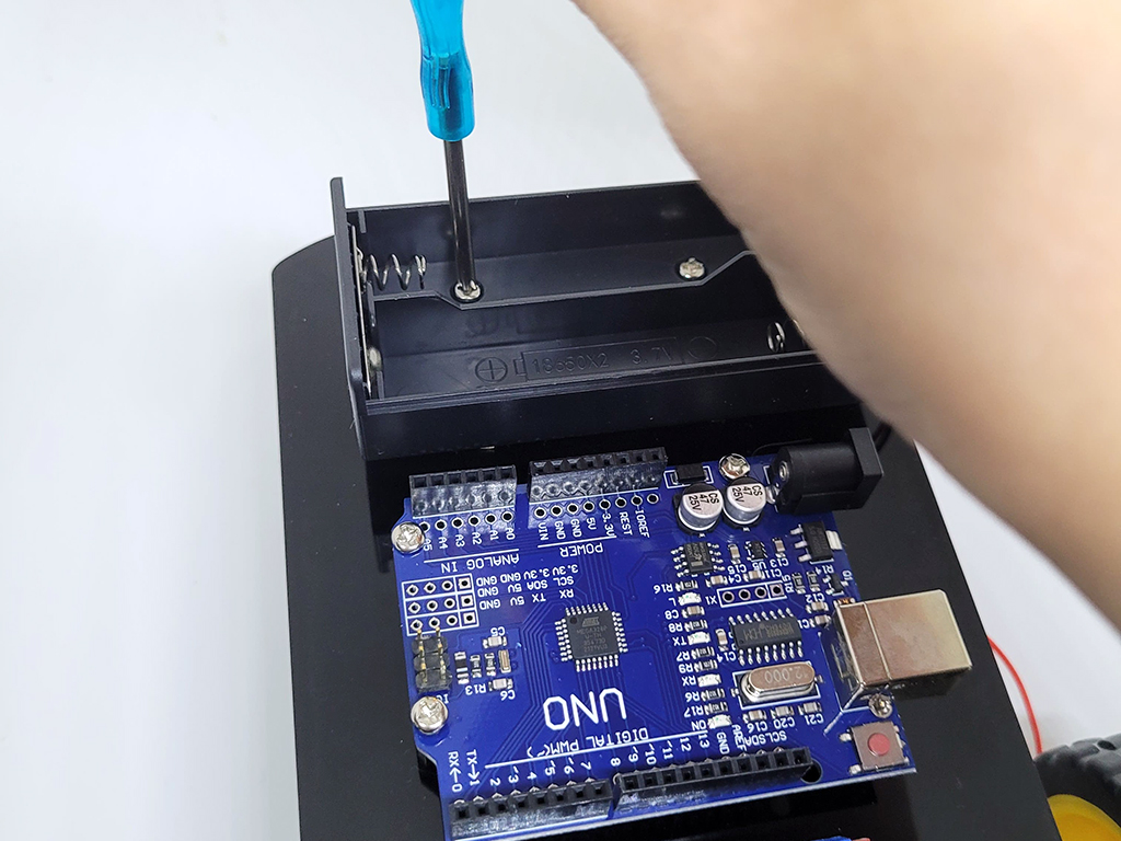
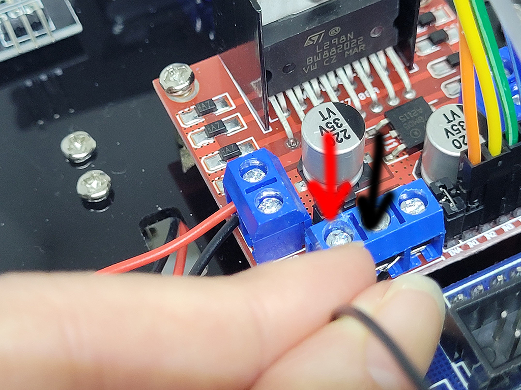
Next, secure the battery enclosure to the chassis with screws as shown Connect up the battery enclosure's red and black wires to the motor controller. You will need to unscrew and then fit the wire into the hole. Then screw to tighten it into place. The red arrow in the photo indicates that's where the red wire should go, and black arrow for the black wire.
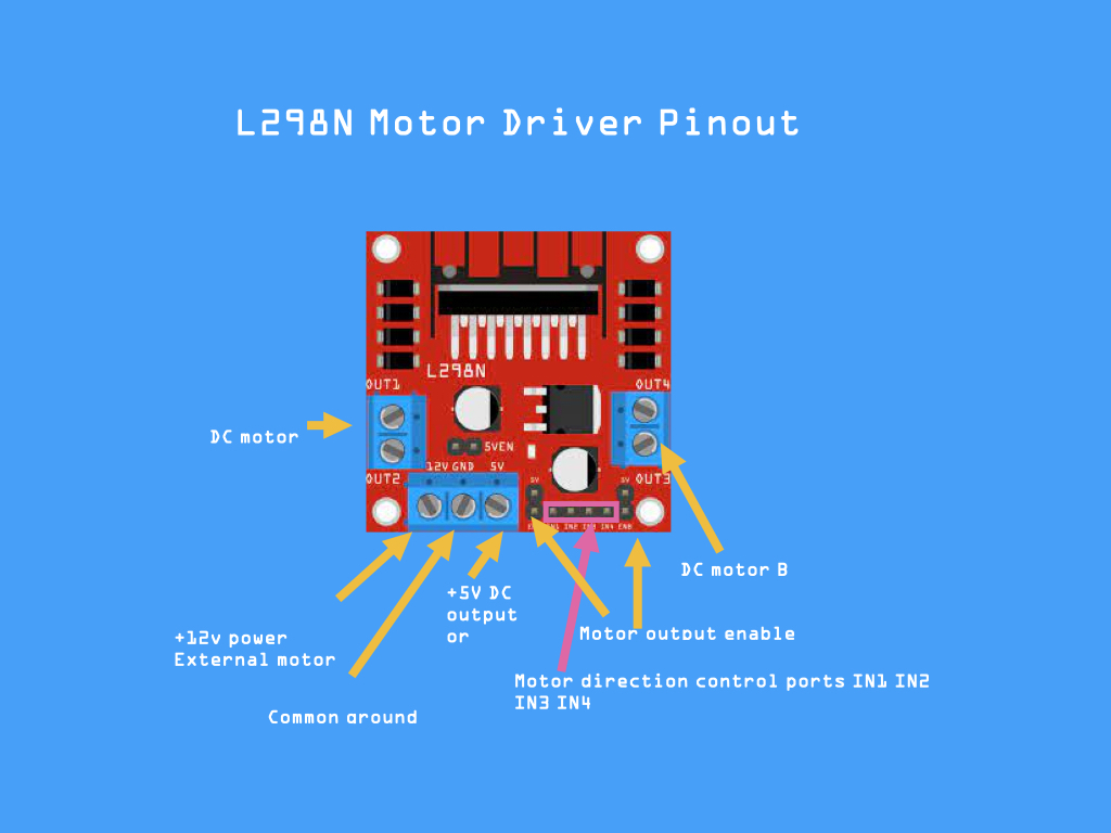
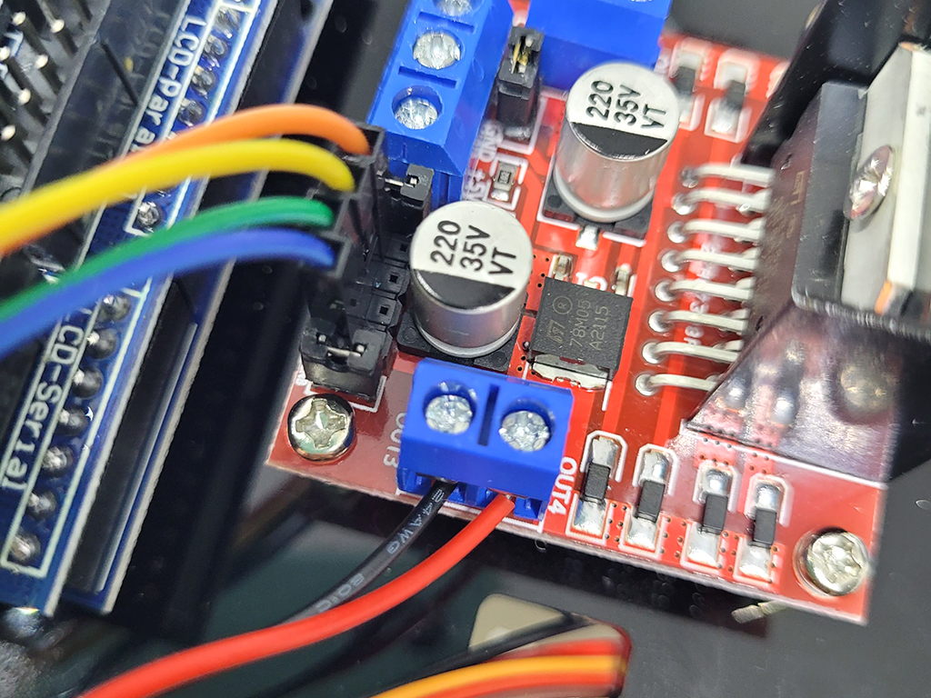
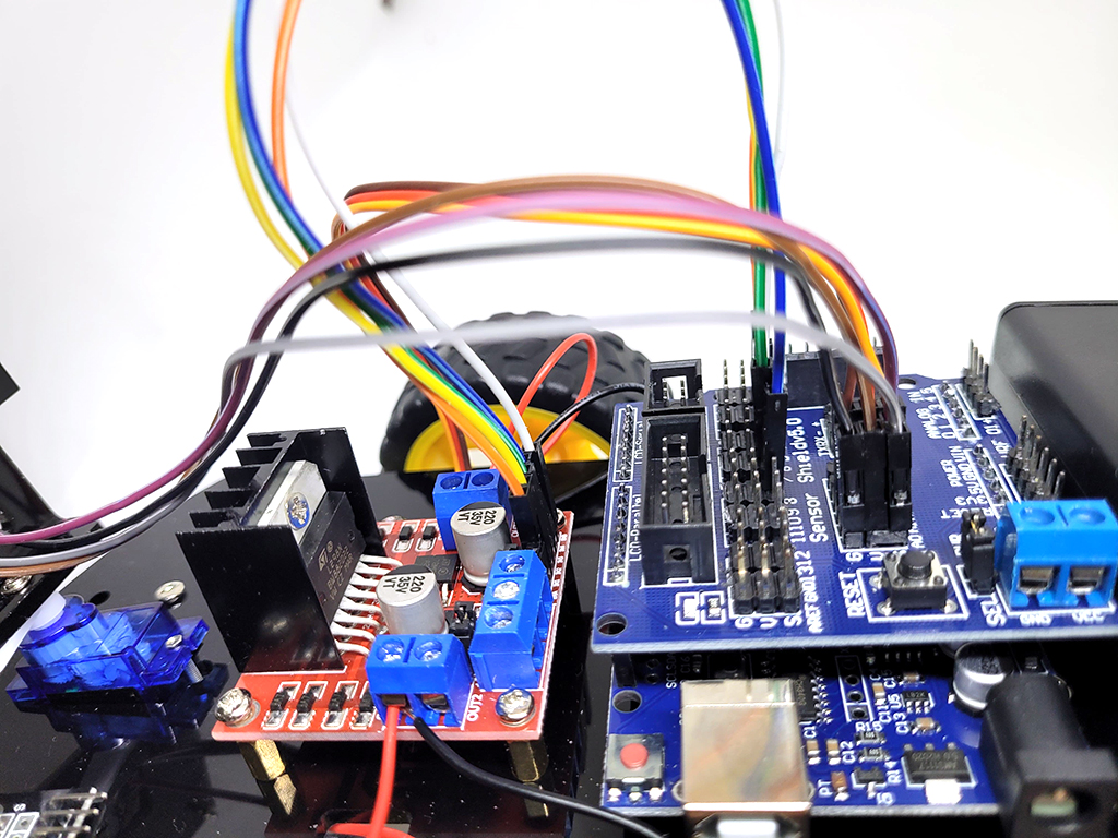
Connect the red and black wires from each motor to the L298N motor driver. These go where it says 'DC motor' on the diagram. So they go on each side of the driver. Now take a look at the diagram shown in the second image of this step. The red and black wires are connected to the DC motor. In the next steps, we will connect the Sensor shield and Arduino.
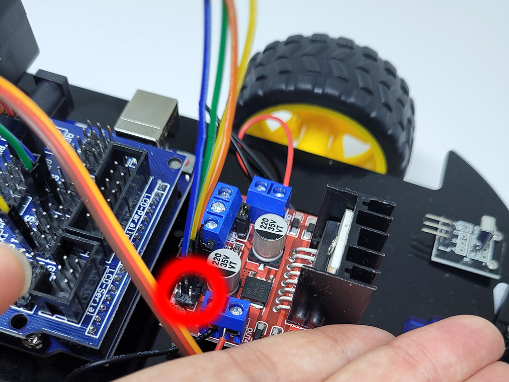
This is an optional step. To change the speed of the motors you can use the EN pins, but these have a plastic cover over them at the moment. So go ahead and remove the two covers on the motor driver if you'd like. You can change the speed with the EN pins using PWM. ENA controls the speed of the left motor and ENB controls the speed of the right motor. Again, this is optional and the motors will still run if you don't connect these to the Arduino.
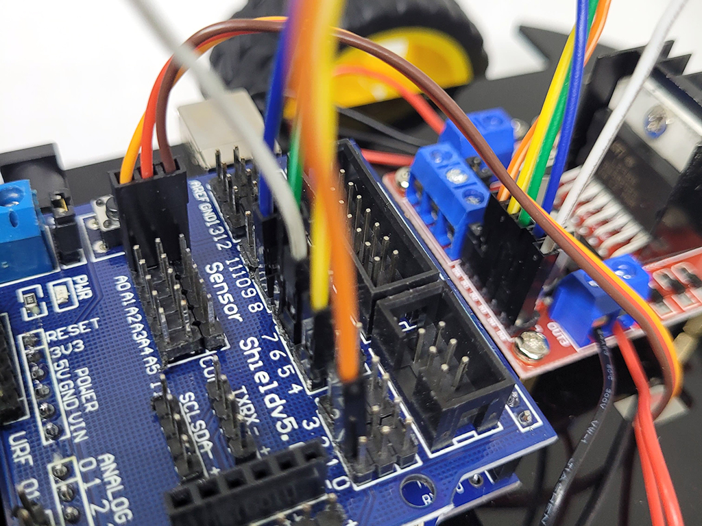
- Connect IN4 on the motor driver to Pin 7 on the sensor shield
- IN3 on the motor driver to Pin 9 on the sensor shield
- IN4 and IN3 will control the left motor.
- IN2 on the motor driver to Pin 8 on the sensor shield
-
- IN1 on the motor driver to Pin 4 on the sensor shield.
- IN2 and IN1 will control the right motor.
Finally, connect four wires to the ultrasonic distance sensor like such:
- GND to G
- VCC to V
- TRIG to 11
- ECHO to 12
Now connect them up to the shield as shown and your wiring is now complete. Please double-check your wiring to this diagram. In the next step, we'll get started with programming our Owl Robot! We also recommend checking out this coloured diagram of the Arduino Sensor Shield V5.0. Edit Me
// defines pins numbers
const int trigPin = 11;
const int echoPin = 12;

// defines variables
long duration;
int distance;

void setup() {
  pinMode(trigPin, OUTPUT); // Make the trigPin an OUTPUT
  pinMode(echoPin, INPUT); // Make the echoPin an INPUT
  Serial.begin(9600); // Setup the Serial Port
}

void loop() {

  // Clear the trigPin
  digitalWrite(trigPin, LOW);
  delayMicroseconds(2);

  // Send a pulse by setting the trigPin Higj for 10 Micro seconds
  digitalWrite(trigPin, HIGH);
  delayMicroseconds(10);
  digitalWrite(trigPin, LOW);

  // Read the length of time for the sound wave to return
  duration = pulseIn(echoPin, HIGH);

  // Calculating the total distance from the object
  distance = duration * 0.034 / 2;

  // Prints the distance to the Serial Port
  Serial.print("The Distance Is: ");
  Serial.println(distance);
}
Upload the following code to the Owl bot. Set your Serial Monitor at a Baud of 9600. Go to Tools > Serial Monitor and view the data being printed to the serial monitor. This value reflects the distance of an object from the ultrasonic distance sensor. Try to move your hand close to or away from it, and see what happens!
int trigPin = 11;      // trig pin of HC-SR04
int echoPin =12;     // Echo pin of HC-SR04

int revleft4 = 7;       //Reverse motion of Left motor
int fwdleft5 = 9;       //Forward motion of Left motor
int revright6 = 8;      //Reverse motion of Right motor
int fwdright7 = 4;      //Forward motion of Right motor

long duration, distance;

void setup() {

  delay(random(500,2000));   // delay for random time
  Serial.begin(9600);
  pinMode(revleft4, OUTPUT);      // set Motor pins as output
  pinMode(fwdleft5, OUTPUT);
  pinMode(revright6, OUTPUT);
  pinMode(fwdright7, OUTPUT);

  pinMode(trigPin, OUTPUT);         // set trig pin as output
  pinMode(echoPin, INPUT);          //set echo pin as input to capture reflected waves
}

void loop() {

  digitalWrite(trigPin, LOW);
  delayMicroseconds(2);
  digitalWrite(trigPin, HIGH);     // send waves for 10 us
  delayMicroseconds(10);
  duration = pulseIn(echoPin, HIGH); // receive reflected waves
  distance = duration / 58.2;   // convert to distance
  delay(10);
    // If you dont get proper movements of your robot then alter the pin numbers
  if (distance > 19)
  {
    digitalWrite(fwdright7, HIGH);                    // move forward
    digitalWrite(revright6, LOW);
    digitalWrite(fwdleft5, HIGH);
    digitalWrite(revleft4, LOW);
  }

  if (distance < 18)
  {
    digitalWrite(fwdright7, LOW);  //Stop
    digitalWrite(revright6, LOW);
    digitalWrite(fwdleft5, LOW);
    digitalWrite(revleft4, LOW);
    delay(500);
    digitalWrite(fwdright7, LOW);      //movebackword
    digitalWrite(revright6, HIGH);
    digitalWrite(fwdleft5, LOW);
    digitalWrite(revleft4, HIGH);
    delay(500);
    digitalWrite(fwdright7, LOW);  //Stop
    digitalWrite(revright6, LOW);
    digitalWrite(fwdleft5, LOW);
    digitalWrite(revleft4, LOW);
    delay(100);
    digitalWrite(fwdright7, HIGH);
    digitalWrite(revright6, LOW);
    digitalWrite(revleft4, LOW);
    digitalWrite(fwdleft5, LOW);
    delay(500);
  }

}
Copy and paste the following code into the Arduino IDE to get started with moving the motors, together with the aid of the ultrasonic distance sensor.