EEPROM and Arduino
Read and write to the EEPROM memory
Written By: Cherie Tan

Difficulty
Medium
Steps
11
When the Arduino board is powered off, all contents of any variable in the Arduino sketch is lost. For values to retain even in the absence of power, you will need to use EEPROM.
In this guide, learn to use Electrically Erasable Programmable Read-Only Memory (EEPROM) by utilising the handy EEPROM library built into the Arduino IDE.
Complete this guide to learn how to restore a device's last state before power was lost. After power has been reinstated, the RGB LED will automatically light up to the last colour it was set to.
Your desktop computer may have gigabytes worth of memory capacity. However, the Arduino Uno in comparison, has just 2 KB of RAM and 32 KB of flash memory. Thankfully, most sketches won't get close to using all its random access memory (RAM), which is a type of volatile memory in which data is lost when you turn the power off. With the Arduino, its RAM is where the sketch creates and manipulates variables when it is running. So, its RAM is only used to hold contents of variables and other data relating to the running of the program.
Flash memory is where the Arduino sketch is stored, and is a type of non-volatile memory. Which means that stored data is kept even when power is lost. Another form of non-volatile memory that the Arduino board has, is EEPROM.
Flash memory is where the Arduino sketch is stored, and is a type of non-volatile memory. Which means that stored data is kept even when power is lost. Another form of non-volatile memory that the Arduino board has, is EEPROM.
EEPROM stands for Electrically Erasable Programmable Read-Only Memory. The Little Bird Uno R3 has 1 KB of EEPROM memory, and the data stored here can be read back when the board is powered on again or when the sketch is reset, and it is not overwritten when the sketch is updated.
One important thing to take note of is that EEPROM has a limited endurance. It has a specified life of 100,000 write/erase cycles, so you may want to be mindful on how often you write to it.
In this guide, we'll show you how to store persistent data to the Arduino board, that will survive a power loss or program reset.
#include <EEPROM.h>To access the internal EEPROM memory, and read or write to it, the EEPROM library is required. It is already included in the Arduino IDE, so to start off just add an include directive to the top of the sketch like so: #include <EEPROM.h>
#include <EEPROM.h>

int addr = 0;

void setup() {
  /** Empty setup. **/
}


void loop() {
  byte val = 17;
  EEPROM.write(addr, val);
}
EEPROM memory can be thought of as an array, where each element is a single byte. To store data to EEPROM, use the write function: EEPROM.write(adr, data);
Its first argument is the address in which the byte will be written to. The second argument is the value to be written, and this value can only be a number in the 0 to 255 range.
Keep in mind that to store data to EEPROM, it needs to be written a byte at a time.
#include <EEPROM.h>

unsigned int addr = 0;

void setup() {
  Serial.begin(9600);
}


void loop() {
  value = EEPROM.read(addr);
  Serial.print("Value at position 0:");
  Serial.print("\t");
  Serial.print(value, DEC);
  Serial.println();
}
If it has not been written to before at that particular address, it will return the maximum value of 255.
In this sketch, the read function is used to read the value stored in address 0 in EEPROM. It is then printed onto the serial monitor.
EEPROM.update(address, val);To increase the life of EEPROM, limit the number of writes to it by using the update function. This reads the address, and checks to see if a value is already present. If it is then there is no need to write to it again.
Remember, reading does not decrease the endurance of EEPROM.
In the next part of this guide, we'll use an RGB LED module with the Arduino board, and store its colour state in EEPROM. The user will be prompted to input a colour mode over in the serial monitor. Later, when the Arduino is powered off, we will use EEPROM to restore its last mode.
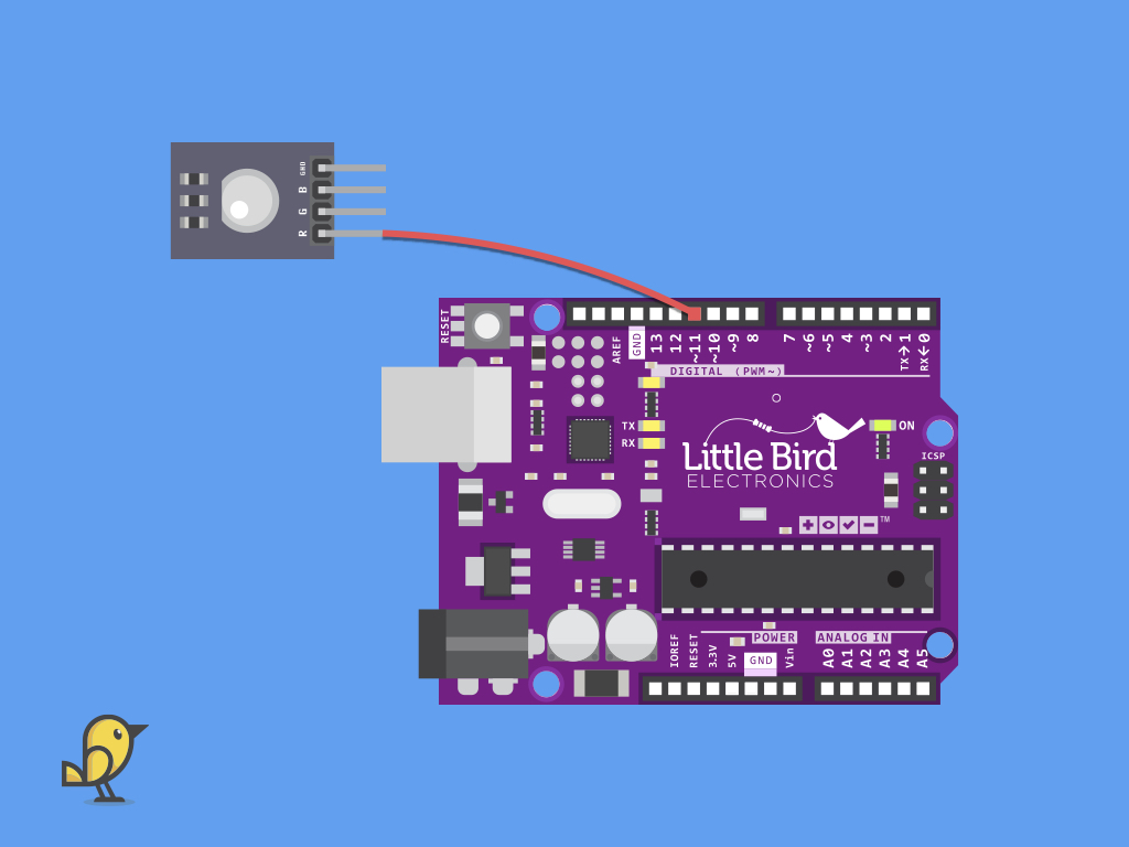
First, connect a F-M jumper wire from R on the RGB LED Module to digital pin 11 on the Little Bird Uno R3.

Connect a F-M jumper wire from G on the RGB LED Module to digital pin 10 on the Little Bird Uno R3.

Connect a F-M jumper wire from B on the RGB LED Module to digital pin 9 on the Little Bird Uno R3.
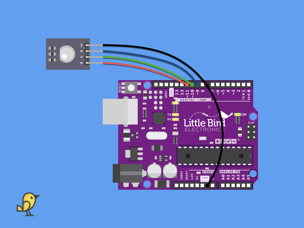
Connect a F-M jumper wire from GND on the RGB LED Module to GND on the Little Bird Uno R3.
String userInput = "";
const int redPin = 11;
const int greenPin = 10;
const int bluePin = 9;
int mode = 0;

void setup() {
  Serial.begin(9600);
  //  Set the RGB LED pins as OUTPUTs
  pinMode(redPin, OUTPUT);
  pinMode(greenPin, OUTPUT);
  pinMode(bluePin, OUTPUT);
}

void loop() {
  Serial.println("Choose LED mode (1, 2, or 3).");
  while (Serial.available() == 0)
  {
    // Wait for user input
  }
  userInput = Serial.readString(); //Reading the input string from serial port
  int mode = userInput.toInt(); //convert readString into an integer

  if (mode == 1) {
    setColor(255, 0, 0); //  Red
  }
  else if (mode == 2) {
    setColor(0, 255, 0); // Green
  }
  else if (mode == 3) {
    setColor(0, 0, 255); // Blue
  }
  else {
    setColor(255, 255, 0);
  }
}

void setColor(int red, int green, int blue) {
  analogWrite(redPin, red);
  analogWrite(greenPin, green);
  analogWrite(bluePin, blue);
}
Go ahead and upload this sketch to the Arduino board.
Navigate to Tools > Serial Monitor.
In this sketch, a user is prompted to choose an LED mode in the Serial monitor. This can either be '1', '2', or '3'.
Choosing mode 1 will result in the RGB LED lighting up in red.
Choosing mode 2 will result in it lighting up in green.
Choosing mode 3 will result in it lighting up in blue.
If a user inputs a string that is not 1, 2, or 3, then the LED will light up in yellow.
Choosing mode 1 will result in the RGB LED lighting up in red.
Choosing mode 2 will result in it lighting up in green.
Choosing mode 3 will result in it lighting up in blue.
If a user inputs a string that is not 1, 2, or 3, then the LED will light up in yellow.
#include <EEPROM.h>

String userInput = "";
const int redPin = 11;
const int greenPin = 10;
const int bluePin = 9;
int addr = 0; // EEPROM address to be used
int mode = 0;

void setup() {
  Serial.begin(9600);
  //  Set the RGB LED pins as OUTPUTs
  pinMode(redPin, OUTPUT);
  pinMode(greenPin, OUTPUT);
  pinMode(bluePin, OUTPUT);
  // Check LED mode on EEPROM using the checkLedMode function
  checkLedMode();
}

void loop() {
  Serial.println("Choose LED mode (1, 2, or 3).");
  while (Serial.available() == 0)
  {
    // Wait for user input
  }
  userInput = Serial.readString(); //Reading the input string from serial port
  int mode = userInput.toInt(); //convert readString into an integer

  if (mode == 1) {
    setColor(255, 0, 0); //  Red
  }
  else if (mode == 2) {
    setColor(0, 255, 0); // Green
  }
  else if (mode == 3) {
    setColor(0, 0, 255); // Blue
  }
  else {
    setColor(255, 255, 0);
  }
  EEPROM.update(addr, mode); // save current mode to the EEPROM
}

void setColor(int red, int green, int blue) {
  analogWrite(redPin, red);
  analogWrite(greenPin, green);
  analogWrite(bluePin, blue);
}

void checkLedMode() {
  mode = EEPROM.read(addr);
  Serial.println("LED mode after restart: ");
  Serial.println(mode);
  if (mode == 1) {
    setColor(255, 0, 0); //  Red
  }
  else if (mode == 2) {
    setColor(0, 255, 0); // Green
  }
  else if (mode == 3) {
    setColor(0, 0, 255); // Blue
  }
  else {
    setColor(255, 255, 0);
  }
}
Replace the existing code with the following, and then set its mode in the Serial Monitor.
Unplug the Arduino board from the computer and then re-connect it again. On power up, the last set mode would have been saved to EEPROM, and the LED will automatically light up to the colour according to its last set mode.