1-Wire and Arduino
A single wire that carries serial data, addresses, and also power!
Written By: Cherie Tan

Difficulty
Medium
Steps
17
1-Wire is a half-duplex bidirectional protocol for microcontrollers and peripherals to communicate with one another.
In this guide, learn about the 1-Wire protocol, and obtain temperature readings from the DS18B20 with a Little Bird Uno R3.
Complete this guide to understand how to use the OneWire library and DallasTemperature library.
In this guide, learn about the 1-Wire protocol, and obtain temperature readings from the DS18B20 with a Little Bird Uno R3.
Complete this guide to understand how to use the OneWire library and DallasTemperature library.
As its name suggests, 1-Wire is a serial bus standard that allows microcontrollers and peripherals to communicate through the use of a single data line (and ground).
It was developed by Dallas Semiconductors and it is used in a variety of sensors, ADCs, and EEPROMs, to name a few examples. However, one of the most commonly used 1-wire devices is the DS18B20 temperature sensor.
In this guide, get started with using the OneWire library, and get temperature readings from the DS18B20 with a Little Bird Uno R3.
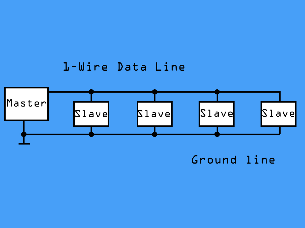
Up to 255 devices can be connected to the same wire.
It is capable of half-duplex bidirectional communication. What's half-duplex communication? A way to think about half-duplex communication is to compare the use of a walkie-talkie with a mobile phone. In the case of a walke-talkie, only one party can talk at one time. On the other hand, a mobile phone allows both parties to talk simultaneously. So with devices using 1-Wire, data can flow in either direction, but only one direction at a time.
While it is slower than I2C, it has the perk of a parasitic power mode. What this means is the slave device can be powered directly from the data line, eliminating the need for any external power supply. So, it utilises a single wire that can transmit both power and information; All this is made possible by the inclusion of an 800 pF capacitor that stores charge from the bus when no data is being transferred, and powers the slave device while the bus is being used for data.
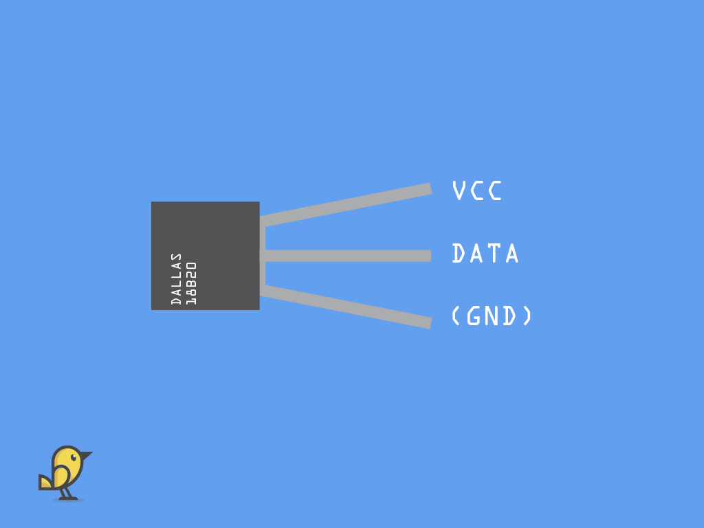
The DS18B20 is a temperature sensor that has three pins:
VCC: In normal power mode, this can be connected to 3.3V o 5V on the Little Bird Uno r3
VCC: In normal power mode, this can be connected to 3.3V o 5V on the Little Bird Uno r3
DATA: This is the data out pin where the temperature data will be output. As the DS18B20 has a built-in ADC, we will connect this to a digital pin.
GND: Ground. What is 'GND'? In electronics, we define a point in a circuit to be a kind of zero volts or 0V reference point, on which to base all other voltage measurements. This point is called ground or GND.
This sensor has an accuracy of +/-0.5 deg C in the range -10 deg C to +85 deg C.
There are two ways to wire up the DS18B20 to the Little Bird Uno R3. In this guide, the DS18B20 will be first connected with a normal power connection. Then, in parasitic power connection.

Connect a black jumper wire from GND on the DS18B20 to GND on the Little Bird Uno r3.
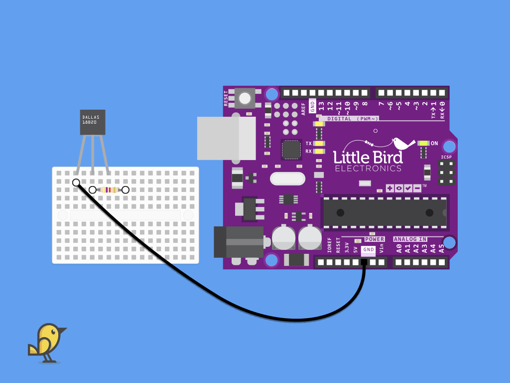
Insert a 4.7k ohm resistor into the breadboard as shown. It should be plugged into the breadboard along the Data pin.

Insert a jumper wire from the breadboard from where Data pin is connected, to digital pin 2 on the Little Bird Uno R3.
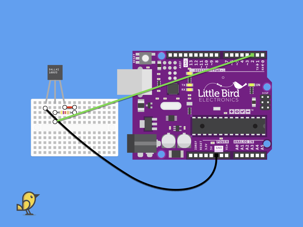
Next, connect red jumper wire to 4.7k ohm resistor on the breadboard.
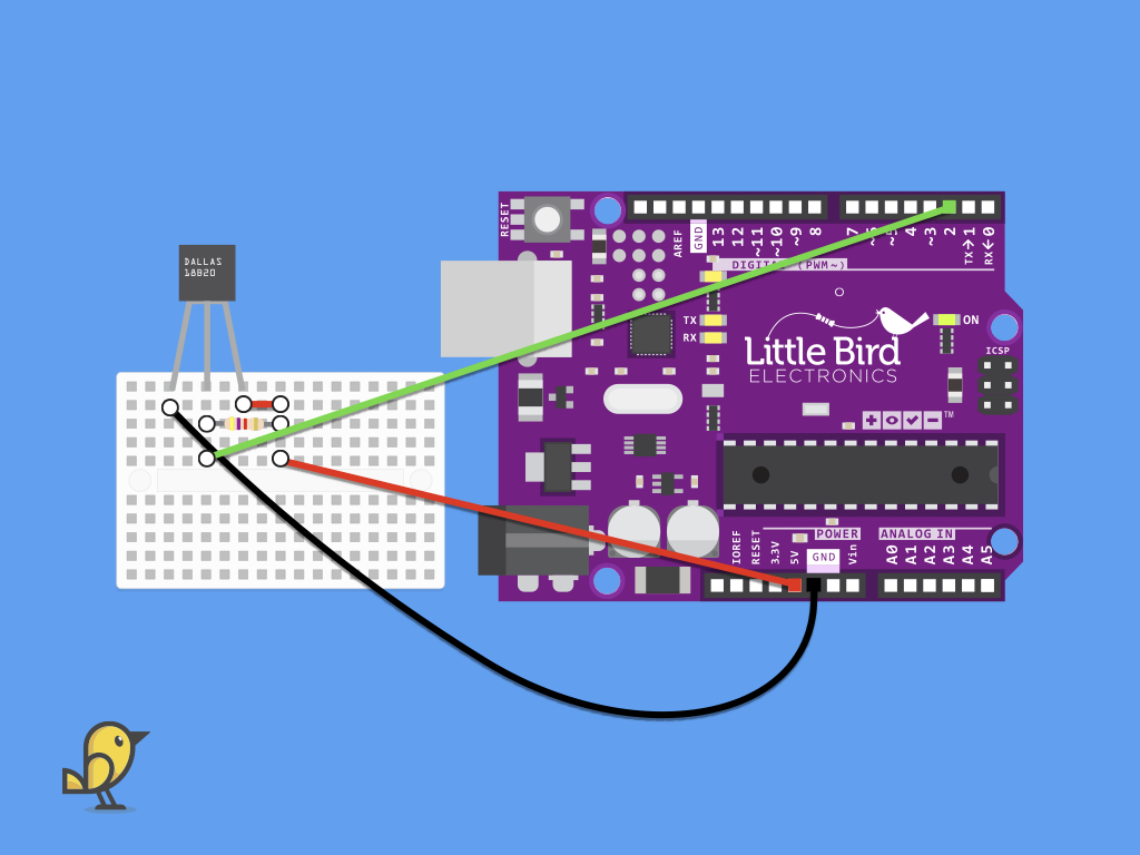
Next, insert a red jumper wire from the breadboard to 5V on the Little Bird Uno R3.
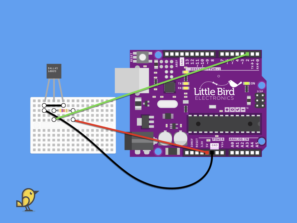
Parasite mode should be used only with a small number of devices, over relatively short distances.
Alternatively, to connect the DS18B20 for use with parasitic power mode, connect the DS18B20's GND pin with a black jumper wire to its VCC pin.
Connect them to GND on the Little Bird Uno R3.
The data pin is the data/parasite power line. This data line still requires the use of a pull-up 4.7k ohm resistor to be connected to +5V.
Connect the data pin to an available digital input pin. In this guide, it is connected to digital pin 2.
#include <OneWire.h>There are two ways to gather temperature data from the DS18B20. First, with just the OneWire library, and second with the DallasTemperature library. If you'd like to use the DallasTemperature library which will simplify the process, jump to Step 16.
The first step is to include the OneWire library with: #include <OneWire.h>
The first step is to include the OneWire library with: #include <OneWire.h>
#include <OneWire.h>

const byte DS18B20_PIN=2;  //define sensor data pin
OneWire ds(DS18B20_PIN); // DS18B20 on pin 2
Next, create a const byte variable named DS18B20 and since the data pin had been connected to digital pin 2 on the Little Bird Uno R3, assign it a value of 2.
Then, to initialize the 1-Wire bus and create a OneWire object, this can be done in a single command:
OneWire ds(DS18B20_PIN)
Its parameter specifies the Arduino pin to be used with the 1-Wire data bus. In this case, we've used the previously created variable as its parameter, DS18B20_PIN that holds the value 2.
OneWire ds(DS18B20_PIN)
Its parameter specifies the Arduino pin to be used with the 1-Wire data bus. In this case, we've used the previously created variable as its parameter, DS18B20_PIN that holds the value 2.
#include <OneWire.h>

const byte DS18B20_PIN=2;  //define sensor data pin
OneWire ds(DS18B20_PIN); // DS18B20 on pin 2

byte data[12]; // buffer for data
byte address[8]; // 64 bit device address
Next, create a byte array, data that will be the buffer for the data.
Next, create a byte array called address.
Each 1-Wire slave device has a 64-bit identification number, which is the device's address on the 1-Wire bus. The first 8 bits constitutes the 'family code' of the device, which lets you know what kind of device it is. For example, the DS18B20 has a family code (Hexadecimal) of 10.
#include <OneWire.h>

const byte DS18B20_PIN = 2; //define sensor data pin
OneWire ds(DS18B20_PIN); // DS18B20 on pin 2

byte data[12]; // buffer for data
byte address[8]; // 64 bit device address

void setup(void)
{
  Serial.begin(9600);
  if (ds.search(address))
  {
    Serial.println("Slave device found!")
  }
  else
  {
    Serial.println("Slave device not found!")
  }
}
If a device is found, it returns true and "Slave device found!" is printed to the serial monitor. Otherwise, it will print, "Slave device not found!".
In setup, we've initialised serial communication at a baud rate of 9600. By doing so, later, temperature readings can be sent to the serial monitor.
Then the OneWire search function is used. It searches for devices on the 1-Wire bus, that is an 8 byte array. If a device is found, it is filled with the device's address and true is returned. If no device is found, false is returned.
Then the OneWire search function is used. It searches for devices on the 1-Wire bus, that is an 8 byte array. If a device is found, it is filled with the device's address and true is returned. If no device is found, false is returned.
#include <OneWire.h>

const byte DS18B20_PIN = 2; //define sensor data pin
OneWire ds(DS18B20_PIN); // DS18B20 on pin 2

byte data[12]; // buffer for data
byte address[8]; // 64 bit device address

void setup(void)
{
  Serial.begin(9600);
  if (address[0] = 0x28)
  {
    Serial.println("DS18B20 family device found!");
  }
  else if (address[0] != 0x28) {
    Serial.print("Device is not a DS18S20 family device.\n");
    return;
  }
}
Alternatively, run this sketch and it will output to the serial monitor whether or not a DS18B20 device is found.
The DS18B20 family code is 28.
#include <OneWire.h>

const byte DS18B20_PIN = 2; //define sensor data pin
OneWire ds(DS18B20_PIN); // DS18B20 on pin 2

byte data[12]; // buffer for data
byte address[8]; // 64 bit device address

void setup(void)
{
  Serial.begin(9600);
  if (address[0] = 0x10)
  {
    Serial.println("DS18B20 family device found!");
  }
  else if (address[0] != 0x10)
  {
    Serial.print("Device is not a DS18S20 family device.\n");
    return;
  }
}

void loop(void) {
  ds.reset();
  ds.select(address);
  ds.write(0x44, true); // starts temperature  conversion, with parasite power on at the end
  delay(1000);

  ds.reset();
  ds.select(address);
  ds.write(0XBE); // This reads the Scratchpad

  for (int i = 0; i < 9; i++) {
    data[i] = ds.read();
  }
  byte MSB = data[1];
  byte LSB = data[0];
  return (((MSB << 8) + LSB ) * 0.0625);
}
Next, in the main loop, the select function is used to select the slave device (based on its address) to be communicated with.
It will communicate with that particular device until another reset.
It will communicate with that particular device until another reset.
Next, the first command is issued, which begins temperature conversion.
You will need to set the right mode to get correct temperature readings:
For Parasite mode,it should read: ds.write(0x44, 1);
For Regular mode, it should read: ds.write(0x44);
For Parasite mode,it should read: ds.write(0x44, 1);
For Regular mode, it should read: ds.write(0x44);
After this command, a reset is performed before the data is then read with the Read ScratchPad command.
For a full list of commands, check out the DS18B20 datasheet.
To actually get temperature readings in degrees Celsius from this data, the most significant byte, MSB, is shifted to the left by 8 bits. Then the LSB is added to it, resulting in a 16-bit integer that is then multiplied by 0.0625.
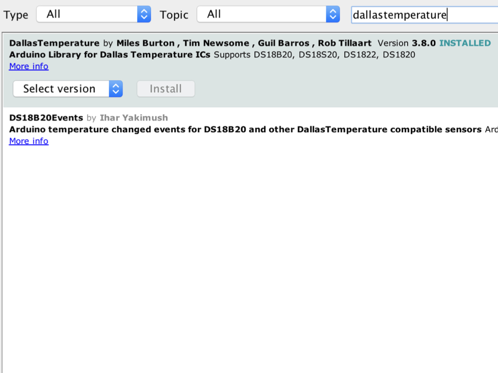
A simpler way to get temperature readings from the DS18B20 is to use the DallasTemperature library. Navigate to Tools > Manage Libraries.
Type 'dallastemperature' into the search field.
Click on the 'Install' button next to DallasTemperature by Miles Burton ...
Once complete, it should state 'INSTALLED'. Click on the 'Close' button to return to the Arduino IDE.
#include <OneWire.h>
#include <DallasTemperature.h>

// Data wire is plugged into digital pin 2 on the Arduino
#define ONE_WIRE_BUS 2

// Setup a oneWire instance to communicate with any OneWire device
OneWire oneWire(ONE_WIRE_BUS);

// Pass oneWire reference to DallasTemperature library
DallasTemperature sensors(&oneWire);

void setup(void)
{
  sensors.begin();  // Start up the library
  Serial.begin(9600);
}

void loop(void)
{
  // Send the command to get temperatures
  sensors.requestTemperatures();

  //print the temperature in Celsius
  Serial.print("Temperature: ");
  Serial.print(sensors.getTempCByIndex(0));
  Serial.print((char)176);//shows degrees character
  Serial.print("C  |  ");

  //print the temperature in Fahrenheit
  Serial.print((sensors.getTempCByIndex(0) * 9.0) / 5.0 + 32.0);
  Serial.print((char)176);//shows degrees character
  Serial.println("F");

  delay(1000);
}
Copy and paste this sketch into the Arduino IDE.
Upload the code to the Little Bird Uno R3.
Navigate to Tools > Serial Monitor